Extrude
Extrude pulls a closed sketch profile along the sketch plane's normal into a solid. It is the operation behind most parts: a plate, a boss on a plate, a pocket in the plate. The same dialog adds material, removes it, or keeps the result as a body of its own.
In the viewport
- Finish a sketch (or select an existing sketch row in the timeline) and click Extrude on the toolbar. Finishing a sketch also offers Extrude directly from the green Finish sketch button.
- Fill in the dialog. A translucent ghost previews the result while you edit, and the statement being written shows under the dialog.
- Click Apply: the timeline gains an Extrude row and the statement is written to the file.
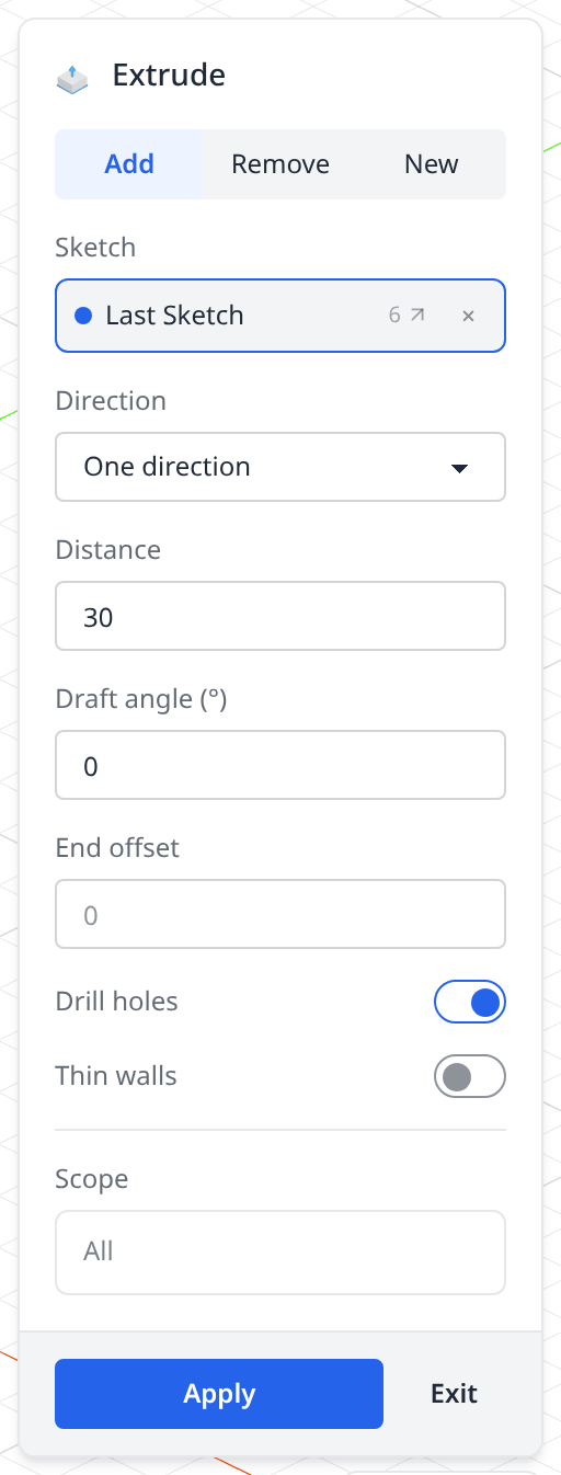
- 1Add / Remove / NewWhat the new material does to the solids already in the scene. Add fuses, New keeps it separate, Remove cuts it away — see Add, New and Remove below.
- 2SketchThe profile being extruded, filled with the last sketch. Click another sketch in the timeline, or its wires in the viewport, to change it. The grey number is the line the sketch was made on; the arrow jumps there.
- 3DirectionOne direction, Symmetric, Two distances, or Up to face — a picked face, the first face or the last face the extrusion meets.
- 4DistanceA number, an expression, or a parameter name. Dragging the ghost in the viewport sets it too. On the Remove tab this becomes Depth, with a Through all toggle beside it.
- 5Draft angleTapers the walls as the extrusion rises. Positive angles pull them inward, negative angles flare them out.
- 6End offsetShifts the end face further along the extrusion direction — handy when the distance comes from a face or a parameter and you need a little more.
- 7Drill holes / Thin wallsDrill holes (on by default) treats profiles nested inside others as holes. Thin walls replaces the filled profile with a wall of the thickness you then type.
- 8ScopeWhich solids the Add or Remove applies to. Left as All it touches everything it meets; pick solids to narrow it.
- 9ApplyWrites the statement and adds the timeline row. Exit closes the dialog and writes nothing.
From sketch to solid
A rectangle on the ground plane, pulled up 30:
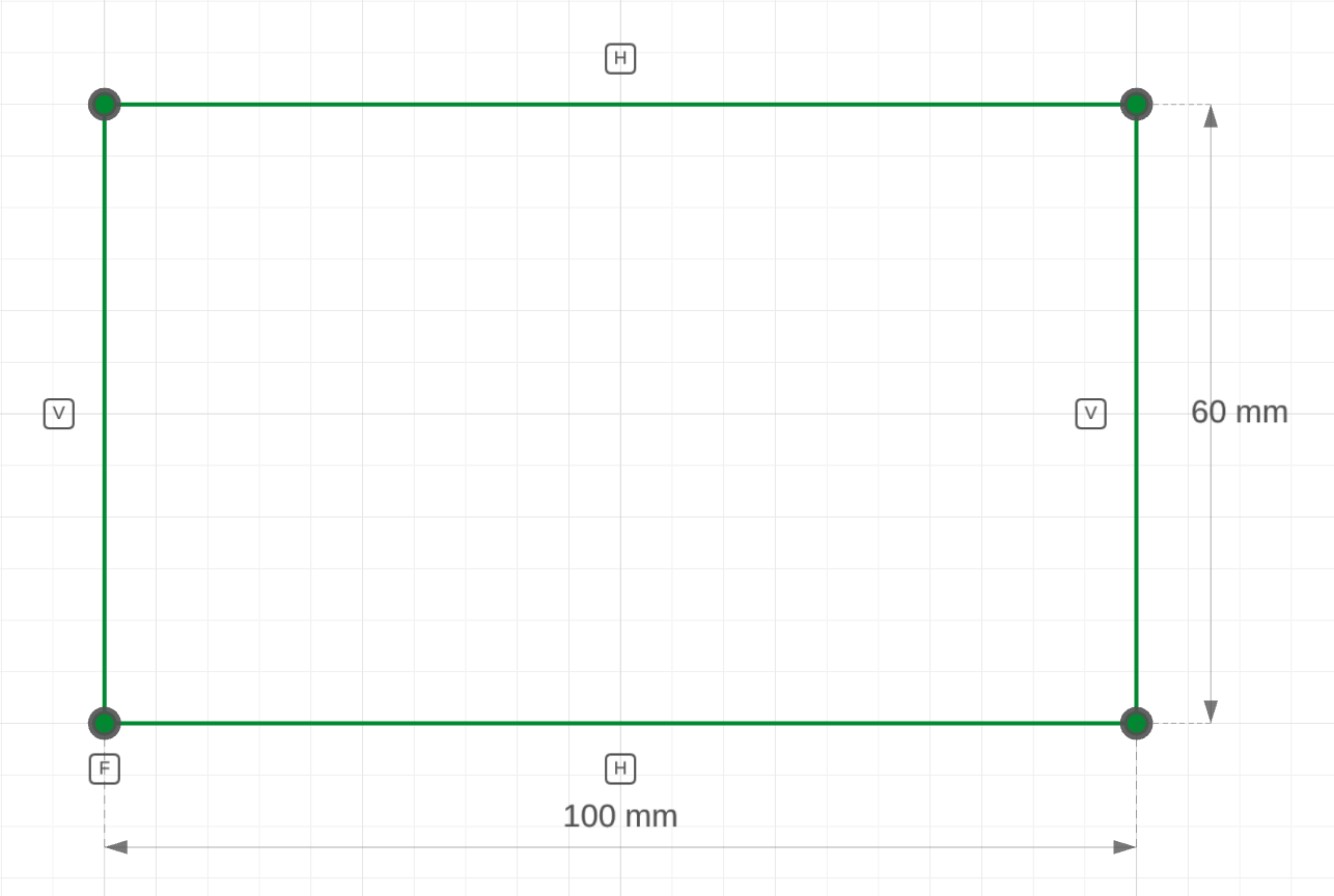
the sketchA closed, fully constrained 100 × 60 rectangle. Nothing solid yet.
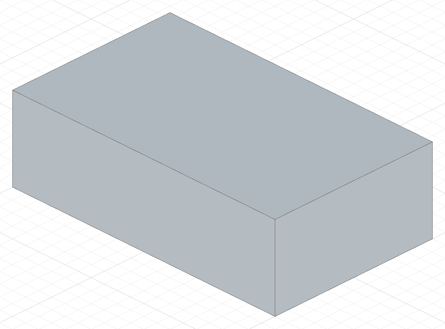
extrude(30)The same profile pulled 30 along the plane normal (+Z for the top plane) — a 100 × 60 × 30 plate.
The sketch
import { sketch, line } from 'fluidcad/core';
import { coincident, distance, fix, horizontal, vertical } from "fluidcad/constraints";

// The starting point of every extrude: a closed, fully constrained profile.
// This one is a 100 x 60 rectangle on the top plane.
sketch("xy", () => {
    const sg1 = line([-50, -30], [50, -30]);
    const sg2 = line([50, -30], [50, 30]);
    const sg3 = line([50, 30], [-50, 30]);
    const sg4 = line([-50, 30], [-50, -30]);
    coincident(sg1.end(), sg2.start());
    coincident(sg2.end(), sg3.start());
    coincident(sg3.end(), sg4.start());
    coincident(sg4.end(), sg1.start());
    horizontal(sg1);
    vertical(sg2);
    horizontal(sg3);
    vertical(sg4);
    fix(sg1.start(), [-50, -30]);
    distance(sg1.start(), sg1.end(), 100);
    distance(sg2.start(), sg2.end(), 60);
  })
The complete file
import { sketch, extrude } from 'fluidcad/core';
import { line } from 'fluidcad/core';
import { coincident, distance, fix, horizontal, vertical } from "fluidcad/constraints";

// A 100 x 60 base plate: a rectangle on the top plane, pulled up 30.
sketch("xy", () => {
    // Four lines drawn at their intended positions — the coordinates are
    // guesses the constraints below turn into an exact 100 x 60 rectangle.
    const sg1 = line([-50, -30], [50, -30]);
    const sg2 = line([50, -30], [50, 30]);
    const sg3 = line([50, 30], [-50, 30]);
    const sg4 = line([-50, 30], [-50, -30]);
    // Coincident joins the corners into a closed loop
    coincident(sg1.end(), sg2.start());
    coincident(sg2.end(), sg3.start());
    coincident(sg3.end(), sg4.start());
    coincident(sg4.end(), sg1.start());
    // Horizontal / vertical square the sides up
    horizontal(sg1);
    vertical(sg2);
    horizontal(sg3);
    vertical(sg4);
    // Fix pins one corner so the profile cannot slide; the two distances
    // set the width and height. The sketch is now fully constrained.
    fix(sg1.start(), [-50, -30]);
    distance(sg1.start(), sg1.end(), 100);
    distance(sg2.start(), sg2.end(), 60);
  })

// Extrude the sketch 30 along the plane's normal (+Z for the top plane).
// `extrude()` takes the last sketch by default; keeping the result in `e`
// gives later features access to its faces and edges (e.endFaces(), ...).
const e = extrude(30)
Everything the dialog can do is a chained method on the statement it writes. The sections below go through the dialog controls one by one and show the code each one produces.
Using a sketch again
An extrude takes its sketch off the screen, but the sketch is not used up. The Sketch picker lists every sketch a feature already used, named after that feature (s · used by Extrude); click its row in the timeline to pick it, and the dialog draws its wires for as long as it holds it. Apply binds the sketch to a variable if it has none and writes extrude(20, s). With region picking the same sketch drives one feature per region. To see a used sketch outside a dialog, click the eye on its timeline row.
Symmetric
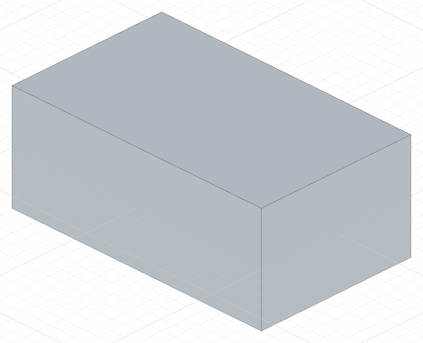
Choose Symmetric under Direction. The profile grows the given distance on both sides of the sketch plane, so the sketch plane ends up in the middle of the solid.
The code behind it
import { sketch, extrude } from 'fluidcad/core';
import { line } from 'fluidcad/core';
import { coincident, distance, fix, horizontal, vertical } from "fluidcad/constraints";

sketch("xy", () => {
    const sg1 = line([-50, -30], [50, -30]);
    const sg2 = line([50, -30], [50, 30]);
    const sg3 = line([50, 30], [-50, 30]);
    const sg4 = line([-50, 30], [-50, -30]);
    coincident(sg1.end(), sg2.start());
    coincident(sg2.end(), sg3.start());
    coincident(sg3.end(), sg4.start());
    coincident(sg4.end(), sg1.start());
    horizontal(sg1);
    vertical(sg2);
    horizontal(sg3);
    vertical(sg4);
    fix(sg1.start(), [-50, -30]);
    distance(sg1.start(), sg1.end(), 100);
    distance(sg2.start(), sg2.end(), 60);
  })

extrude(40).symmetric()
Two different distances per side are the Two distances direction: extrude(20, 5).
Draft angle
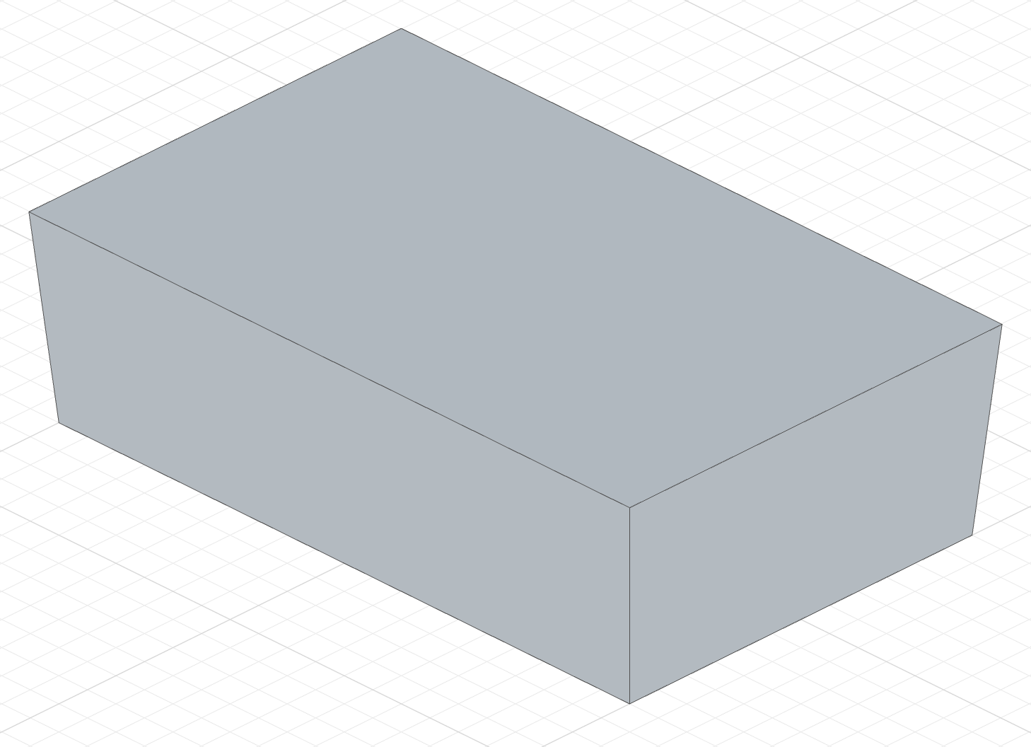
Type an angle in the Draft field. Positive angles taper the walls inward as the extrusion rises, negative angles flare them outward.
The code behind it
import { sketch, extrude } from 'fluidcad/core';
import { line } from 'fluidcad/core';
import { coincident, distance, fix, horizontal, vertical } from "fluidcad/constraints";

sketch("xy", () => {
    const sg1 = line([-50, -30], [50, -30]);
    const sg2 = line([50, -30], [50, 30]);
    const sg3 = line([50, 30], [-50, 30]);
    const sg4 = line([-50, 30], [-50, -30]);
    coincident(sg1.end(), sg2.start());
    coincident(sg2.end(), sg3.start());
    coincident(sg3.end(), sg4.start());
    coincident(sg4.end(), sg1.start());
    horizontal(sg1);
    vertical(sg2);
    horizontal(sg3);
    vertical(sg4);
    fix(sg1.start(), [-50, -30]);
    distance(sg1.start(), sg1.end(), 100);
    distance(sg2.start(), sg2.end(), 60);
  })

extrude(30).draft(5)
Up to face
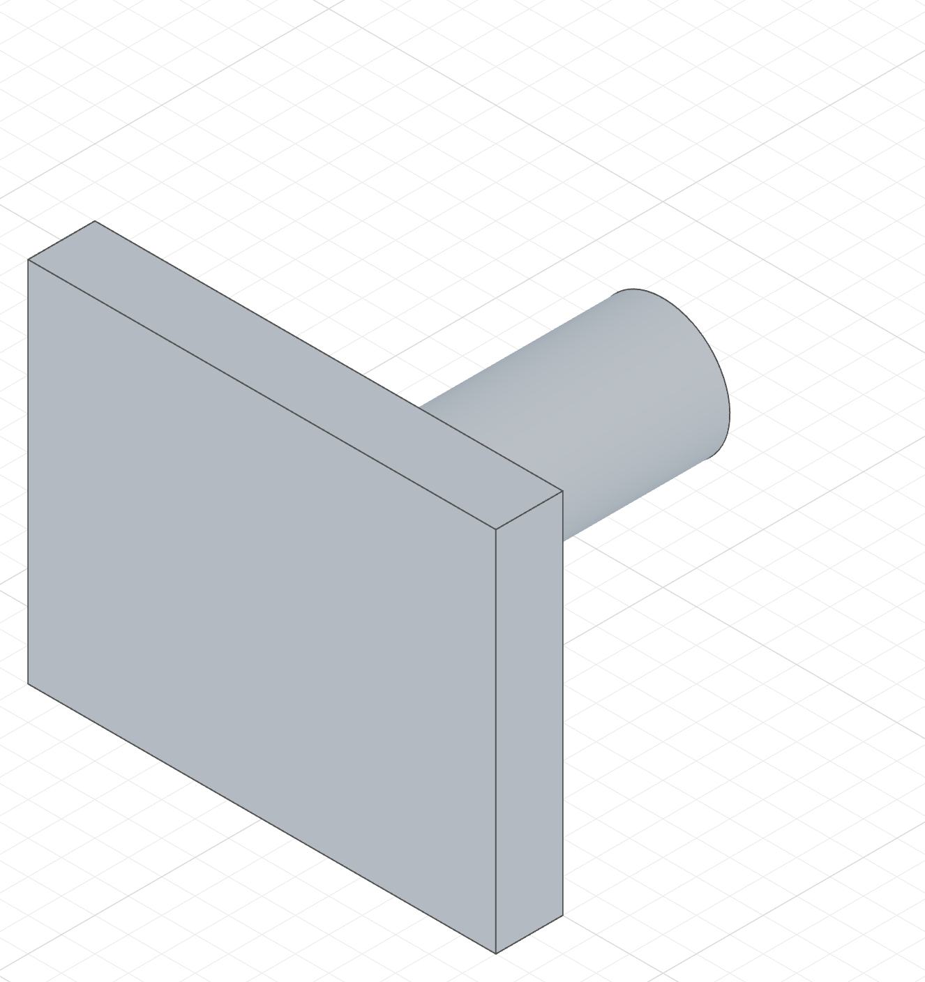
Choose Up to face under Direction and click the face the extrusion should stop at. The Distance field is replaced by a face pick slot.
The extrusion always travels along the sketch plane's normal, so the face has to be on that side of the sketch. The front plane's normal points along −Y, for example, so a boss sketched on it runs toward negative Y and can only reach faces that lie that way.
The code behind it
The face is written as a select() with a face filter, so the reference survives re-renders. The boss stops exactly where it meets that face — change the wall's position and the boss follows.
import { select, sketch, extrude, circle, line } from 'fluidcad/core';
import { face } from 'fluidcad/filters';
import { coincident, diameter, distance, fix, horizontal, vertical } from "fluidcad/constraints";

// A wall standing 100 mm in front of the origin. Its near side is the face
// the boss below has to reach.
sketch("xy", () => {
    const sg1 = line([-70, -120], [70, -120]);
    const sg2 = line([70, -120], [70, -100]);
    const sg3 = line([70, -100], [-70, -100]);
    const sg4 = line([-70, -100], [-70, -120]);
    coincident(sg1.end(), sg2.start());
    coincident(sg2.end(), sg3.start());
    coincident(sg3.end(), sg4.start());
    coincident(sg4.end(), sg1.start());
    horizontal(sg1);
    vertical(sg2);
    horizontal(sg3);
    vertical(sg4);
    fix(sg1.start(), [-70, -120]);
    distance(sg1.start(), sg1.end(), 140);
    distance(sg2.start(), sg2.end(), 20);
  })
extrude(110)

// The face to stop at — the wall side that looks back at the origin.
const targetFace = select(face().onPlane("xz", 100))

// The boss profile, on the front plane. That plane's normal points along −Y,
// straight at the wall, so the extrusion travels toward it.
sketch("front", () => {
    const c = circle([0, 55], 40);
    fix(c.center(), [0, 55]);
    diameter(c, 40);
  })

extrude(targetFace);
Blending with non-planar faces
When the target face is curved, the end of the extrusion takes the shape of that surface instead of staying flat. A square bracket run into a round pipe comes out saddled around it:
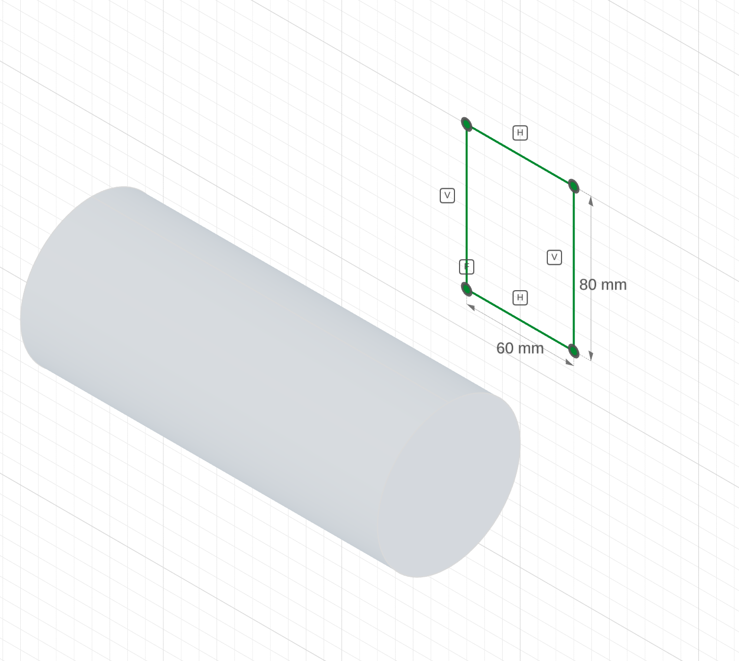
a flat rectangleA Ø80 pipe, and a flat 60 × 80 rectangle sketched on the front plane facing it.
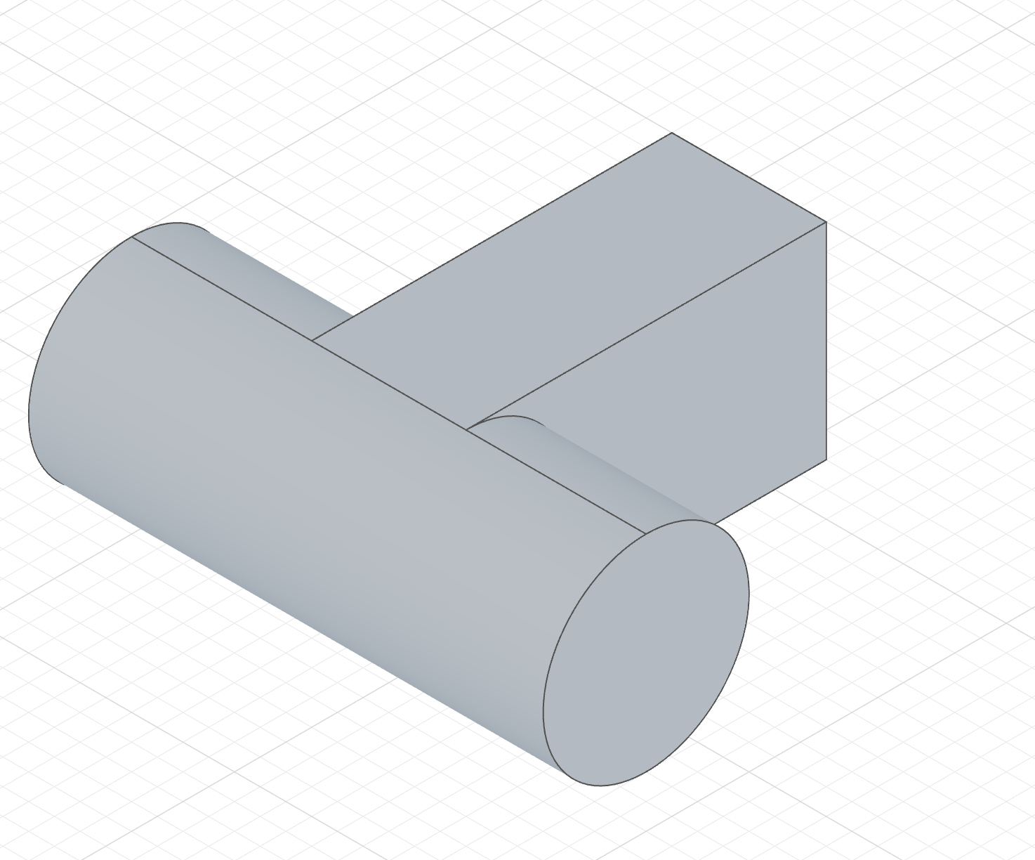
extrude(pipeWall)The bracket runs up to the pipe and its end face becomes a slice of the pipe's cylinder, so the two blend instead of clipping through each other.
The code behind it
import { select, sketch, extrude, circle, line } from 'fluidcad/core';
import { face } from 'fluidcad/filters';
import { coincident, diameter, distance, fix, horizontal, vertical } from "fluidcad/constraints";

// A Ø80 pipe running left to right, 140 mm in front of the origin.
sketch("yz", () => {
    const c = circle([-140, 60], 80);
    fix(c.center(), [-140, 60]);
    diameter(c, 80);
  })
extrude(200).symmetric()

// The face to stop at — the pipe's curved wall.
const pipeWall = select(face().cylinder())

// The bracket profile: a flat 60 x 80 rectangle on the front plane, whose
// normal points at the pipe.
sketch("front", () => {
    const sg1 = line([-30, 20], [30, 20]);
    const sg2 = line([30, 20], [30, 100]);
    const sg3 = line([30, 100], [-30, 100]);
    const sg4 = line([-30, 100], [-30, 20]);
    coincident(sg1.end(), sg2.start());
    coincident(sg2.end(), sg3.start());
    coincident(sg3.end(), sg4.start());
    coincident(sg4.end(), sg1.start());
    horizontal(sg1);
    vertical(sg2);
    horizontal(sg3);
    vertical(sg4);
    fix(sg1.start(), [-30, 20]);
    distance(sg1.start(), sg1.end(), 60);
    distance(sg2.start(), sg2.end(), 80);
  })

// The extrusion stops on the pipe: its end face is a slice of the pipe's
// cylinder, so the bracket lands tangent to it instead of clipping it.
extrude(pipeWall);
First and last face
Up to face also offers first face and last face: the nearest or the farthest face the extrusion runs into along its direction, with nothing to pick. Both walk along the sketch normal, so the same sketch gives two different lengths depending on which you choose:
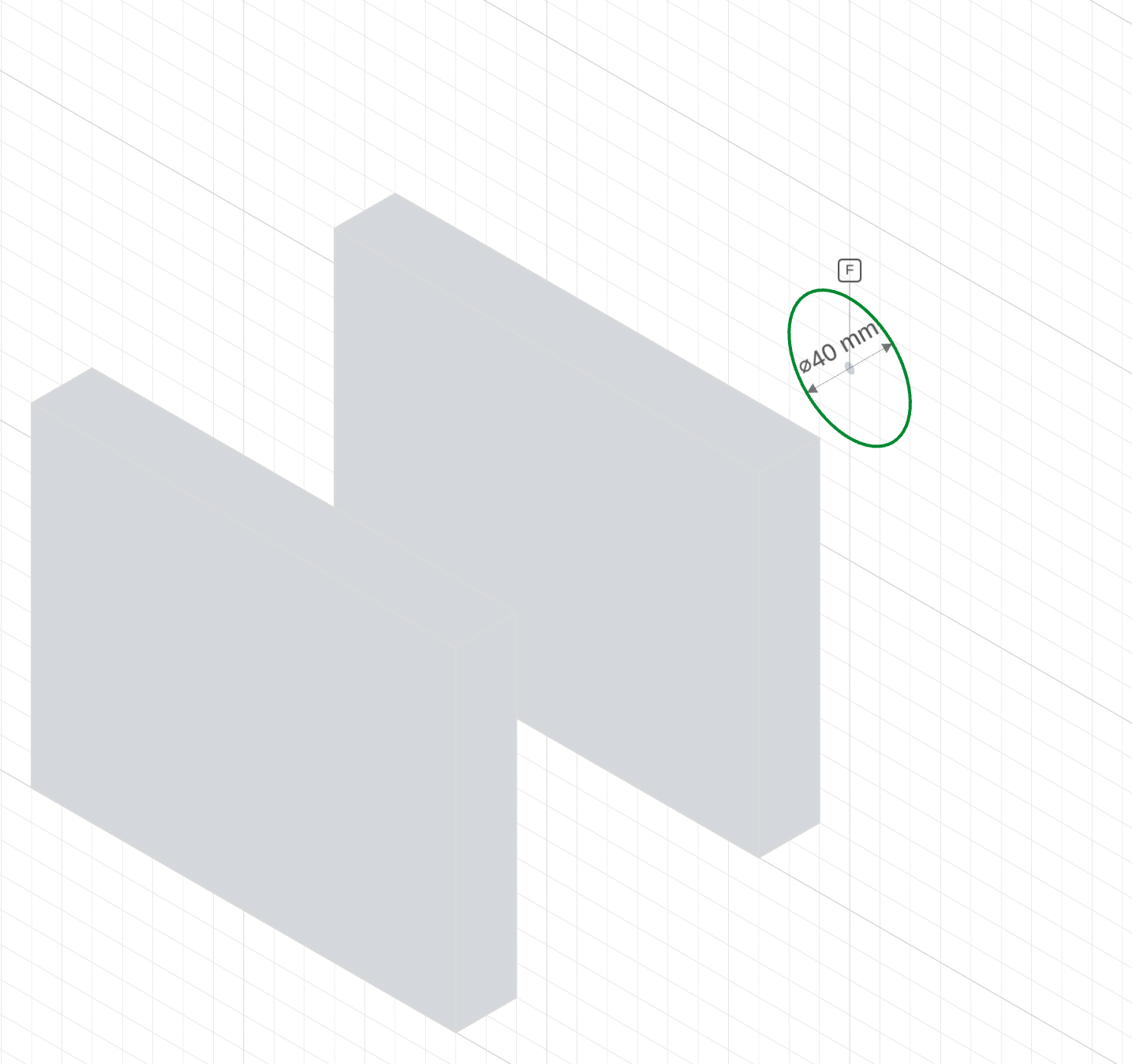
two wallsTwo walls, 80 mm and 180 mm in front of the origin, and a Ø40 rod profile on the front plane pointing at them.
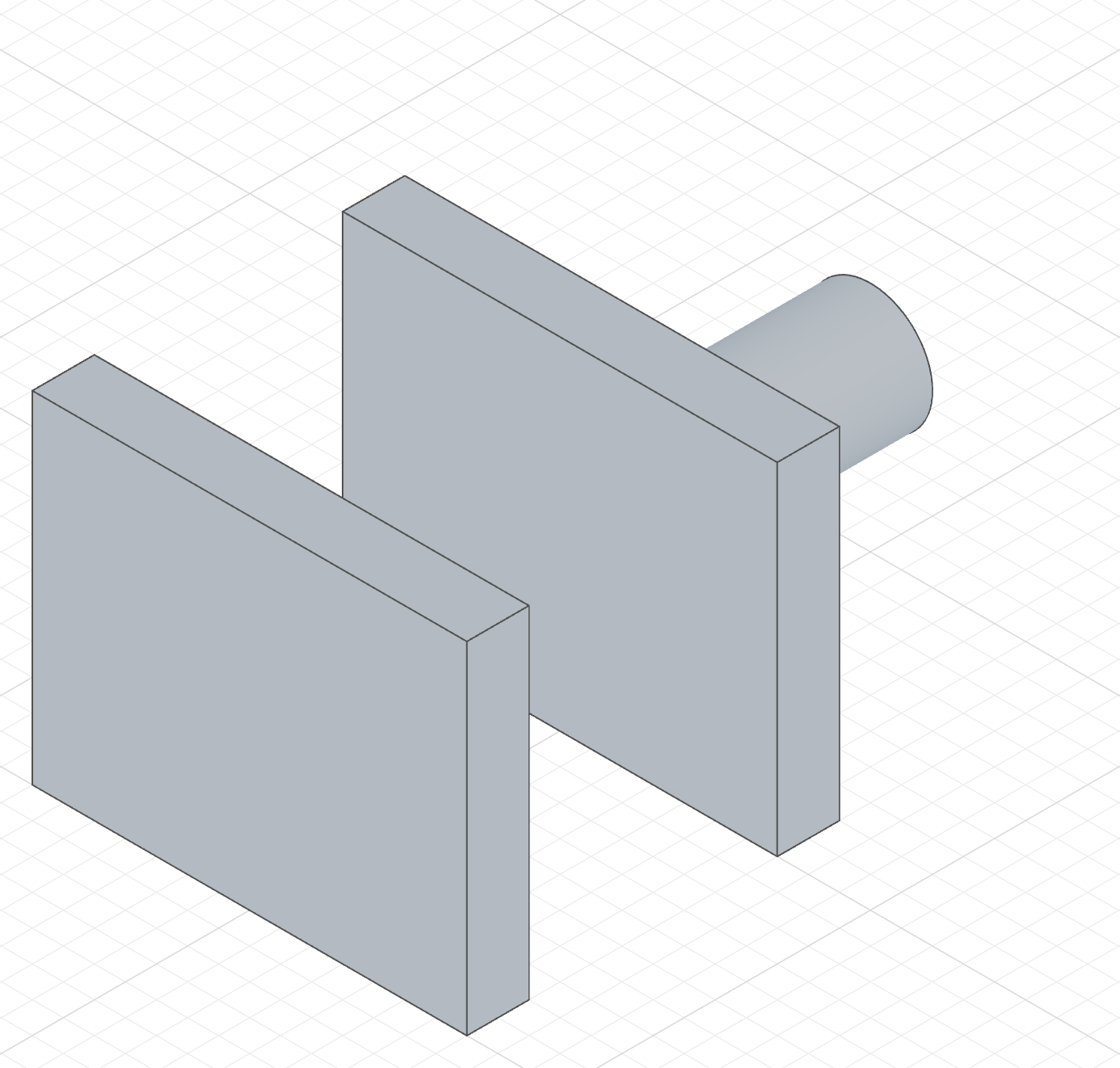
extrude('first-face')The rod stops at the near wall — the first face it meets.
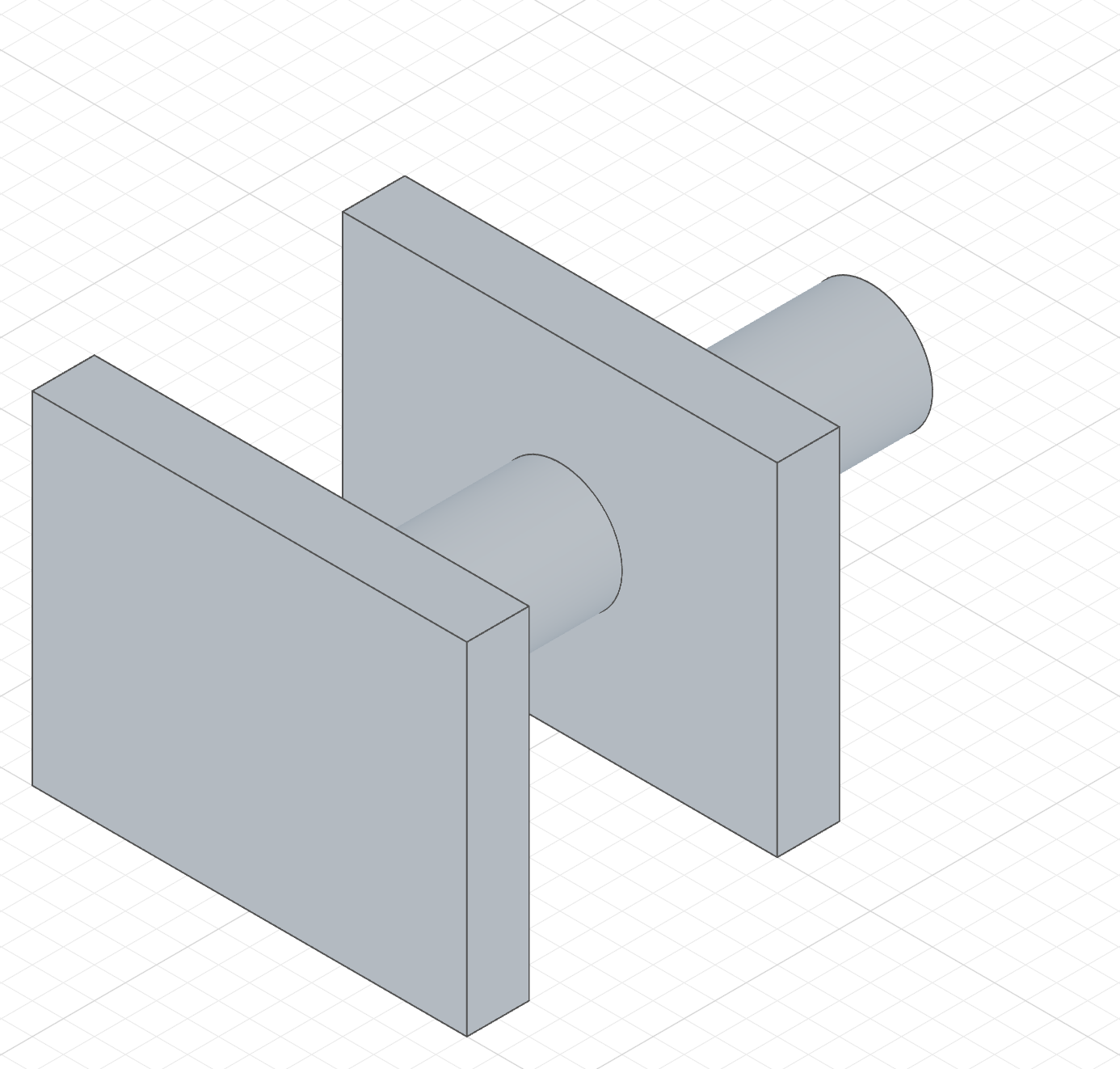
extrude('last-face')The rod runs through the near wall, crosses the gap and ends at the back of the far wall — the last face it meets.
The first-face column's code
The last-face column changes only the highlighted line, to extrude('last-face').
import { sketch, extrude, circle, line } from 'fluidcad/core';
import { coincident, diameter, distance, fix, horizontal, vertical } from "fluidcad/constraints";

// Two upright walls, 80 mm and 180 mm in front of the origin.
sketch("xy", () => {
    const sg1 = line([-70, -100], [70, -100]);
    const sg2 = line([70, -100], [70, -80]);
    const sg3 = line([70, -80], [-70, -80]);
    const sg4 = line([-70, -80], [-70, -100]);
    coincident(sg1.end(), sg2.start());
    coincident(sg2.end(), sg3.start());
    coincident(sg3.end(), sg4.start());
    coincident(sg4.end(), sg1.start());
    horizontal(sg1);
    vertical(sg2);
    horizontal(sg3);
    vertical(sg4);
    fix(sg1.start(), [-70, -100]);
    distance(sg1.start(), sg1.end(), 140);
    distance(sg2.start(), sg2.end(), 20);
  })
extrude(110)

sketch("xy", () => {
    const sg5 = line([-70, -200], [70, -200]);
    const sg6 = line([70, -200], [70, -180]);
    const sg7 = line([70, -180], [-70, -180]);
    const sg8 = line([-70, -180], [-70, -200]);
    coincident(sg5.end(), sg6.start());
    coincident(sg6.end(), sg7.start());
    coincident(sg7.end(), sg8.start());
    coincident(sg8.end(), sg5.start());
    horizontal(sg5);
    vertical(sg6);
    horizontal(sg7);
    vertical(sg8);
    fix(sg5.start(), [-70, -200]);
    distance(sg5.start(), sg5.end(), 140);
    distance(sg6.start(), sg6.end(), 20);
  })
extrude(110)

// A Ø40 rod profile on the front plane. Its normal points along −Y, so the
// extrusion runs at both walls in turn.
sketch("front", () => {
    const c = circle([0, 55], 40);
    fix(c.center(), [0, 55]);
    diameter(c, 40);
  })

// The nearest face the extrusion runs into: the near wall's front side.
extrude('first-face');
Up to face, first face and last face currently work with planar and cylindrical target faces only.
Add, New and Remove
The three tabs at the top of the dialog decide how the extrusion meets the solids already in the scene. The pictures below all start from the same place — a 60 mm cube, and a Ø50 circle on a plane halfway up it that overlaps the cube's right-hand side by 10:
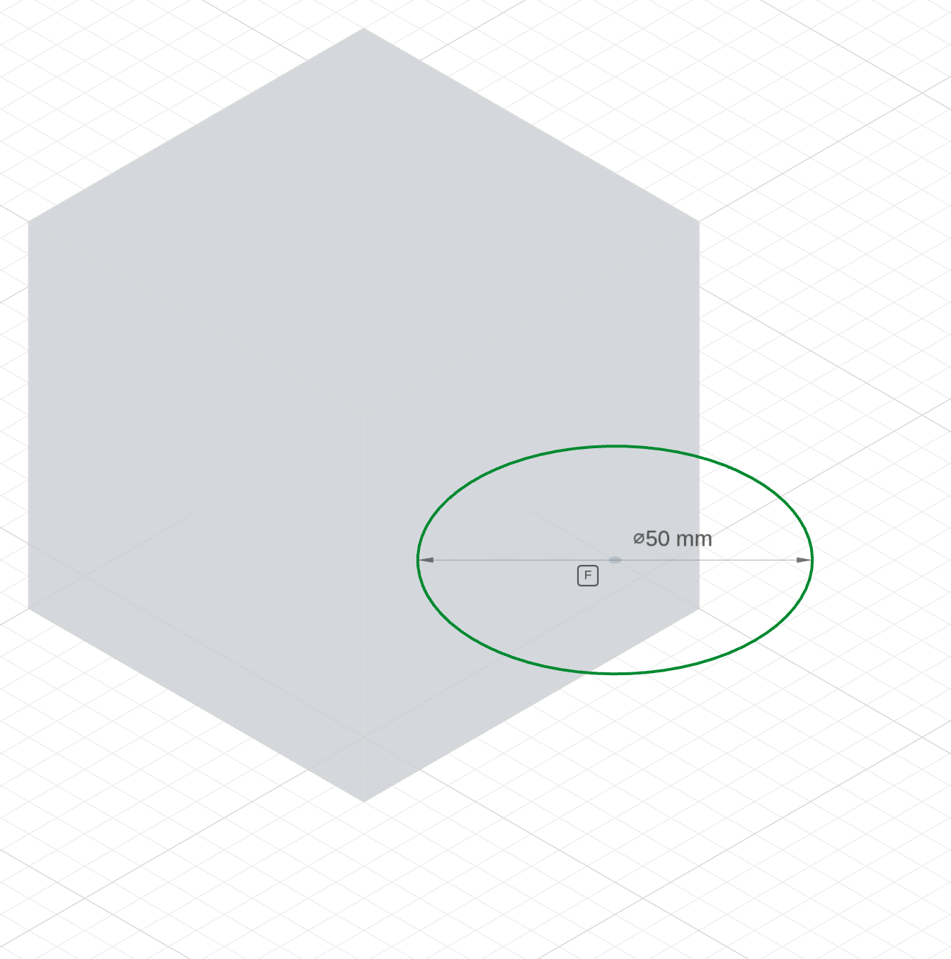
The starting point
The circle sits on a plane through the middle of the cube rather than on the ground so that, with Symmetric on, the same 60 mm reaches the ground and the top in every tab — a Remove runs into the material and an Add runs out along it, and here the cylinder does both.
import { sketch, plane, extrude, circle, line } from 'fluidcad/core';
import { coincident, diameter, distance, fix, horizontal, vertical } from "fluidcad/constraints";

// The base part every column shares: a 60 mm cube standing on the ground plane.
sketch("xy", () => {
    const sg1 = line([-30, -30], [30, -30]);
    const sg2 = line([30, -30], [30, 30]);
    const sg3 = line([30, 30], [-30, 30]);
    const sg4 = line([-30, 30], [-30, -30]);
    coincident(sg1.end(), sg2.start());
    coincident(sg2.end(), sg3.start());
    coincident(sg3.end(), sg4.start());
    coincident(sg4.end(), sg1.start());
    horizontal(sg1);
    vertical(sg2);
    horizontal(sg3);
    vertical(sg4);
    fix(sg1.start(), [-30, -30]);
    distance(sg1.start(), sg1.end(), 60);
    distance(sg2.start(), sg2.end(), 60);
  })
extrude(60)

// The feature profile: a Ø50 circle on a plane halfway up the cube, centred
// 45 to the right so it overlaps the cube's right-hand side by 10. Extruding
// symmetrically from this plane grows 30 up and 30 down — the same height as
// the cube — so the cylinder stands on the ground beside the cube and runs
// into it.
sketch(plane("xy", { offset: 30 }), () => {
    const c = circle([45, 0], 50);
    fix(c.center(), [45, 0]);
    diameter(c, 50);
  })
Symmetric is on in all three, so the cylinder is the same height as the cube and stands beside it on the ground. Only the tab changes between the results:
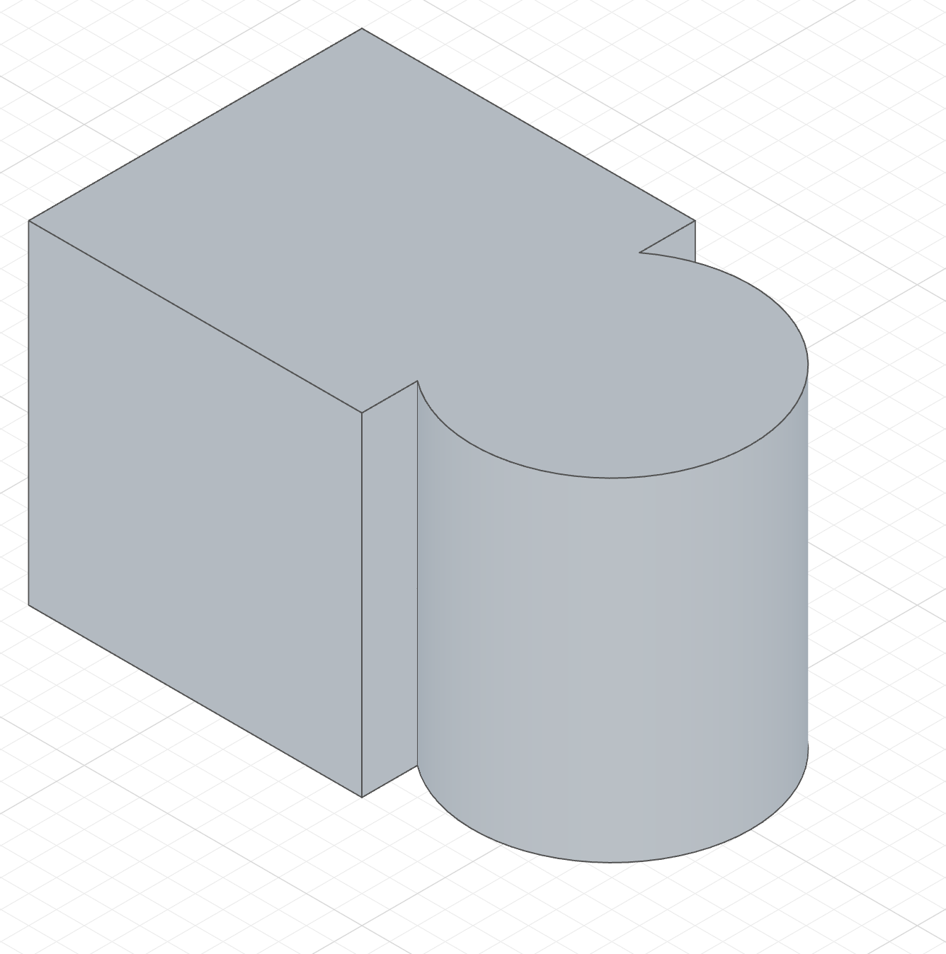
extrude(60).symmetric()The cylinder fuses with the cube where the two overlap — one body, no seam inside the overlap.
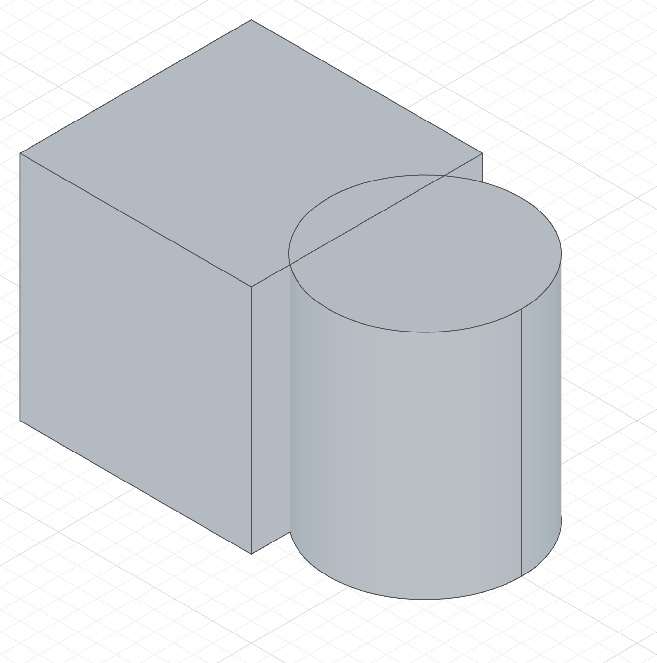
extrude(60).symmetric().new()The same cylinder, kept separate. The Shapes panel lists two solids, the edge where the cylinder passes through the cube stays drawn, and later features on the cube leave the cylinder alone.
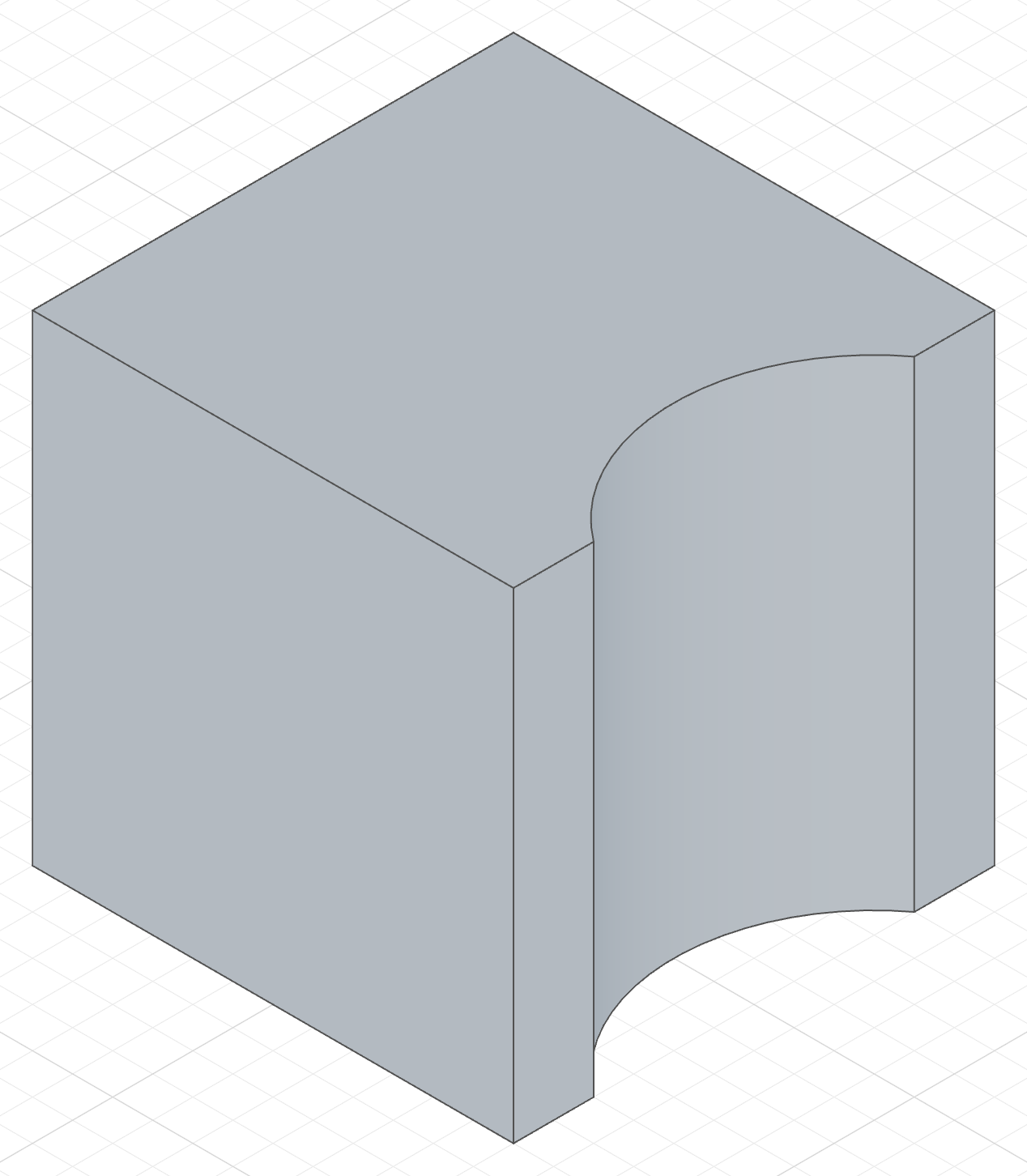
cut(60).symmetric()The cylinder's volume is carved out of the cube instead — a full-height round scallop 10 deep in the right-hand face, and nothing added beside it.
The Add column's code
The New column ends the highlighted line with .new(); the Remove column replaces it with cut(60).symmetric(). Everything above the highlighted line is identical in the three files.
import { sketch, plane, extrude, circle, line } from 'fluidcad/core';
import { coincident, diameter, distance, fix, horizontal, vertical } from "fluidcad/constraints";

// The base part every column shares: a 60 mm cube standing on the ground plane.
sketch("xy", () => {
    const sg1 = line([-30, -30], [30, -30]);
    const sg2 = line([30, -30], [30, 30]);
    const sg3 = line([30, 30], [-30, 30]);
    const sg4 = line([-30, 30], [-30, -30]);
    coincident(sg1.end(), sg2.start());
    coincident(sg2.end(), sg3.start());
    coincident(sg3.end(), sg4.start());
    coincident(sg4.end(), sg1.start());
    horizontal(sg1);
    vertical(sg2);
    horizontal(sg3);
    vertical(sg4);
    fix(sg1.start(), [-30, -30]);
    distance(sg1.start(), sg1.end(), 60);
    distance(sg2.start(), sg2.end(), 60);
  })
extrude(60)

// The feature profile: a Ø50 circle on a plane halfway up the cube, centred
// 45 to the right so it overlaps the cube's right-hand side by 10. Extruding
// symmetrically from this plane grows 30 up and 30 down — the same height as
// the cube — so the cylinder stands on the ground beside the cube and runs
// into it.
sketch(plane("xy", { offset: 30 }), () => {
    const c = circle([45, 0], 50);
    fix(c.center(), [45, 0]);
    diameter(c, 50);
  })

// Add tab, Symmetric direction: a Ø50 cylinder the height of the cube, fused
// with it — one solid, no seam where they meet.
extrude(60).symmetric();
Three things to know about the Remove tab:
- It cuts into the material — the depth runs opposite the sketch plane's normal, the way a drill entering the face you sketched on does. Add and New go the other way, out along the normal.
- The dialog writes
cut(). It is the same feature asextrude().remove(), and both accept every modifier on this page (symmetric, draft, thin, up to face, region picking). - Through all replaces the depth with "as far as the solid goes" —
cut()with no argument.
To limit an Add or Remove to particular solids, chain .scope(a, b) after .add() or .remove(); the dialog exposes this as the Scope slot.
Cutting a pocket
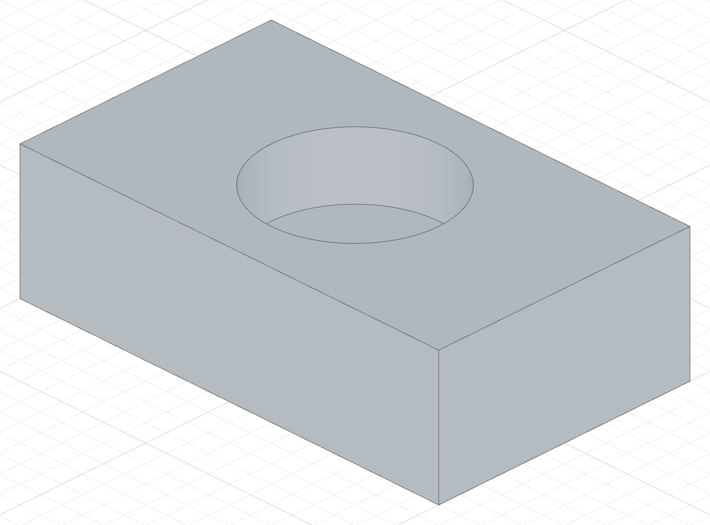
A pocket is a sketch on a face plus an extrude on the Remove tab:
The code behind it
import { sketch, extrude, cut } from 'fluidcad/core';
import { circle, line } from 'fluidcad/core';
import { coincident, distance, fix, horizontal, vertical } from "fluidcad/constraints";

sketch("xy", () => {
    // Four lines drawn at their intended positions — the coordinates are
    // guesses the constraints below turn into an exact 100 x 60 rectangle.
    const sg1 = line([-50, -30], [50, -30]);
    const sg2 = line([50, -30], [50, 30]);
    const sg3 = line([50, 30], [-50, 30]);
    const sg4 = line([-50, 30], [-50, -30]);
    // Coincident joins the corners into a closed loop
    coincident(sg1.end(), sg2.start());
    coincident(sg2.end(), sg3.start());
    coincident(sg3.end(), sg4.start());
    coincident(sg4.end(), sg1.start());
    // Horizontal / vertical square the sides up
    horizontal(sg1);
    vertical(sg2);
    horizontal(sg3);
    vertical(sg4);
    // Fix pins one corner so the profile cannot slide; the two distances
    // set the width and height. The sketch is now fully constrained.
    fix(sg1.start(), [-50, -30]);
    distance(sg1.start(), sg1.end(), 100);
    distance(sg2.start(), sg2.end(), 60);
  })

const box = extrude(30)

// A second sketch on the top face of the box: the pocket's outline.
sketch(box.endFaces(), () => {
    circle([0, 0], 40);
  })

// Remove tab, depth 15: the circle is cut 15 deep into the box.
// cut(15) is the same feature as extrude(15).remove().
cut(15)
Through all
Through all on the Remove tab, or cut() with no distance, removes the profile through the whole solid:
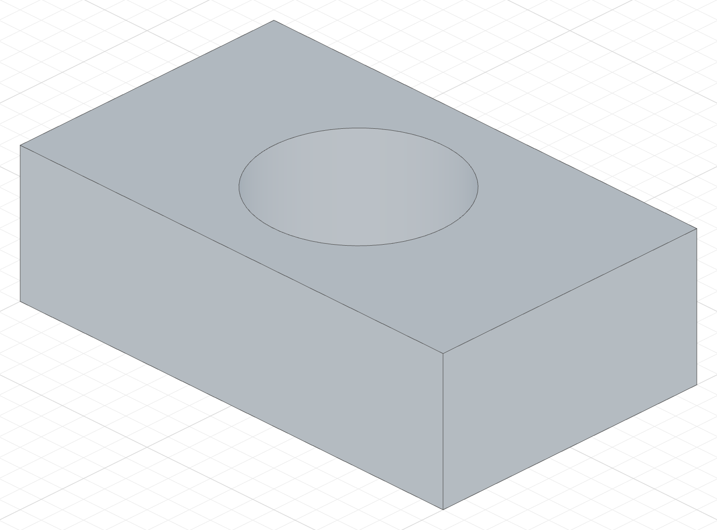
The code behind it
import { sketch, extrude, cut } from 'fluidcad/core';
import { circle, line } from 'fluidcad/core';
import { coincident, distance, fix, horizontal, vertical } from "fluidcad/constraints";

sketch("xy", () => {
    // Four lines drawn at their intended positions — the coordinates are
    // guesses the constraints below turn into an exact 100 x 60 rectangle.
    const sg1 = line([-50, -30], [50, -30]);
    const sg2 = line([50, -30], [50, 30]);
    const sg3 = line([50, 30], [-50, 30]);
    const sg4 = line([-50, 30], [-50, -30]);
    // Coincident joins the corners into a closed loop
    coincident(sg1.end(), sg2.start());
    coincident(sg2.end(), sg3.start());
    coincident(sg3.end(), sg4.start());
    coincident(sg4.end(), sg1.start());
    // Horizontal / vertical square the sides up
    horizontal(sg1);
    vertical(sg2);
    horizontal(sg3);
    vertical(sg4);
    // Fix pins one corner so the profile cannot slide; the two distances
    // set the width and height. The sketch is now fully constrained.
    fix(sg1.start(), [-50, -30]);
    distance(sg1.start(), sg1.end(), 100);
    distance(sg2.start(), sg2.end(), 60);
  })

const box = extrude(30)

// The hole's outline, sketched on the top face.
sketch(box.endFaces(), () => {
    circle([0, 0], 40);
  })

// Through all: no depth, so the circle is cut through the whole solid.
cut()
A cut also accepts a target face, 'first-face' or 'last-face', exactly like Up to face above: cut(targetFace), cut('first-face').
Thin walls
Turn on Thin and type a thickness. Instead of filling the profile, the extrusion offsets the profile's edges by the thickness and extrudes the band between them — a wall.
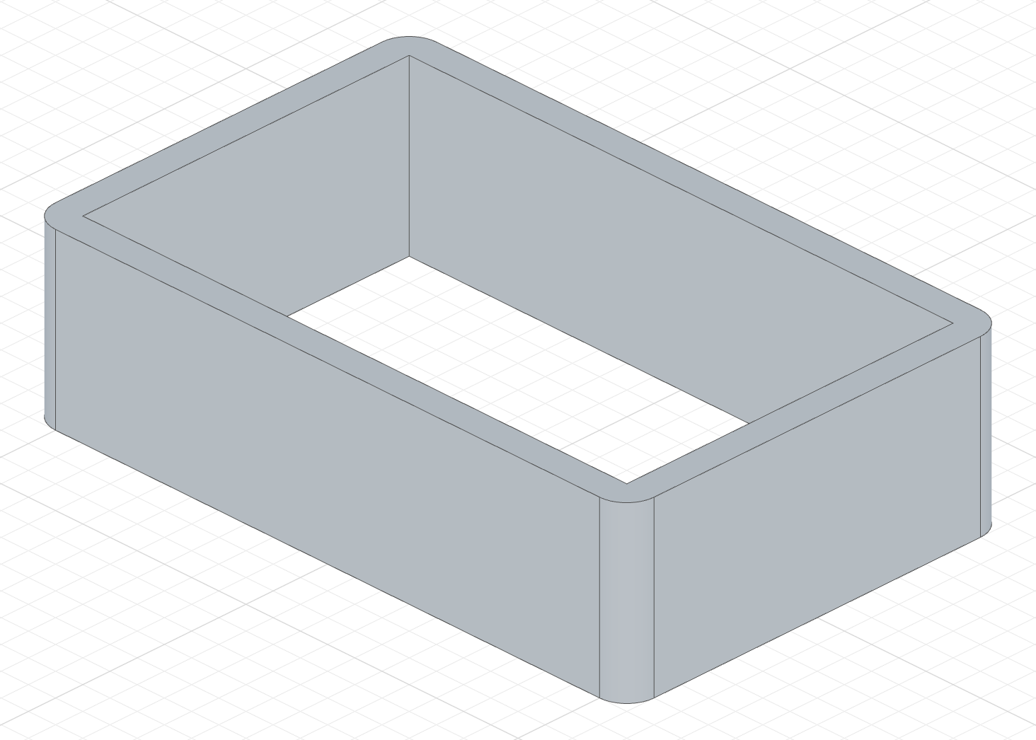
The code behind it
import { sketch, extrude } from 'fluidcad/core';
import { line } from 'fluidcad/core';
import { coincident, distance, fix, horizontal, vertical } from "fluidcad/constraints";

sketch("xy", () => {
    const sg1 = line([-50, -30], [50, -30]);
    const sg2 = line([50, -30], [50, 30]);
    const sg3 = line([50, 30], [-50, 30]);
    const sg4 = line([-50, 30], [-50, -30]);
    coincident(sg1.end(), sg2.start());
    coincident(sg2.end(), sg3.start());
    coincident(sg3.end(), sg4.start());
    coincident(sg4.end(), sg1.start());
    horizontal(sg1);
    vertical(sg2);
    horizontal(sg3);
    vertical(sg4);
    fix(sg1.start(), [-50, -30]);
    distance(sg1.start(), sg1.end(), 100);
    distance(sg2.start(), sg2.end(), 60);
  })

extrude(30).thin(5)
A positive thickness offsets outward, a negative one inward:
extrude(30).thin(5)    // 5 units outward
extrude(30).thin(-5)   // 5 units inward
Thin in the three modes
Thin combines with every tab. A 60 mm cube with a Ø50 circle sketched on its right-hand face, Thin on with a thickness of 3:
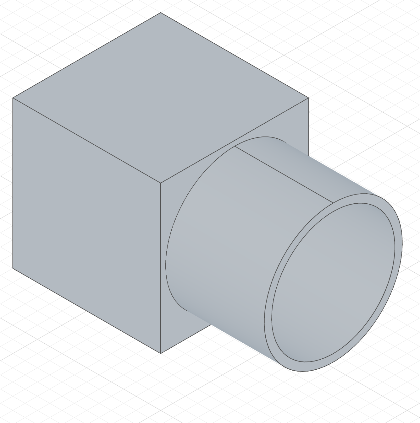
extrude(40).thin(3)A tube instead of a rod — a spigot fused with the cube.
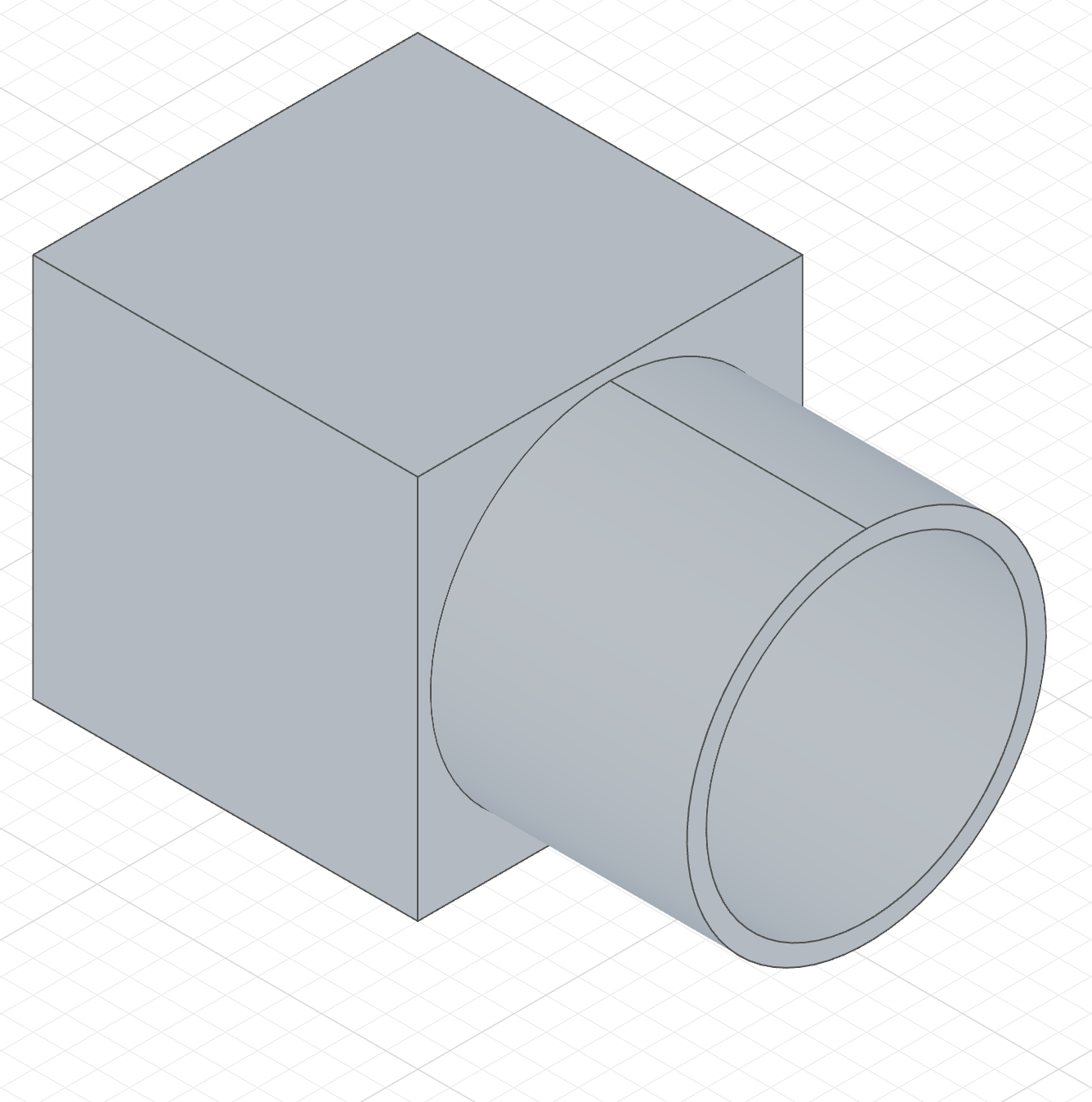
extrude(40).thin(3).new()The same tube as a body of its own.
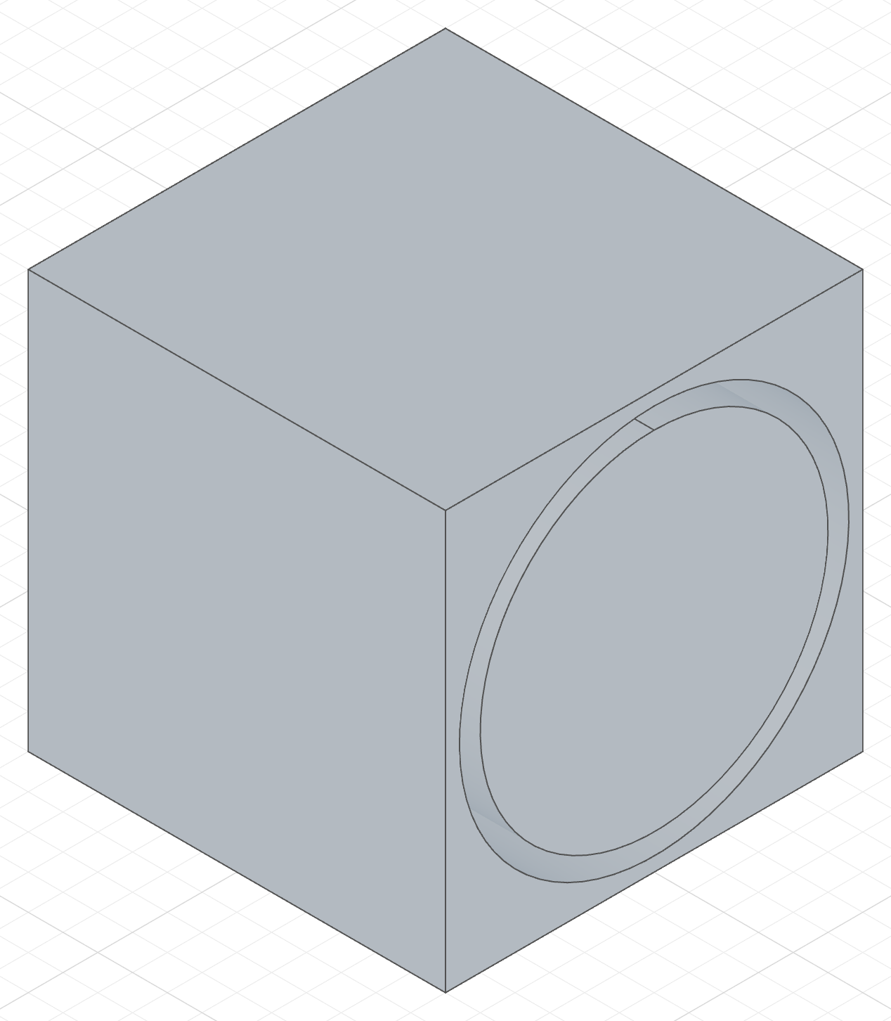
cut(40).thin(3)Only the wall is cut — a 3-wide ring groove 40 deep, with the core left standing.
The Add column's code
import { sketch, plane, extrude, circle, line } from 'fluidcad/core';
import { coincident, diameter, distance, fix, horizontal, vertical } from "fluidcad/constraints";

// The base part every column shares: a 60 mm cube.
sketch("xy", () => {
    const sg1 = line([-30, -30], [30, -30]);
    const sg2 = line([30, -30], [30, 30]);
    const sg3 = line([30, 30], [-30, 30]);
    const sg4 = line([-30, 30], [-30, -30]);
    coincident(sg1.end(), sg2.start());
    coincident(sg2.end(), sg3.start());
    coincident(sg3.end(), sg4.start());
    coincident(sg4.end(), sg1.start());
    horizontal(sg1);
    vertical(sg2);
    horizontal(sg3);
    vertical(sg4);
    fix(sg1.start(), [-30, -30]);
    distance(sg1.start(), sg1.end(), 60);
    distance(sg2.start(), sg2.end(), 60);
  })
extrude(60)

// The feature profile: a Ø50 circle on the cube's right-hand face. The face
// normal points away from the cube, so an extrusion grows out sideways and a
// cut bores straight in.
sketch(plane("yz", { offset: 30 }), () => {
    const c = circle([0, 30], 50);
    fix(c.center(), [0, 30]);
    diameter(c, 50);
  })

// Add tab, Thin on: a 3 mm wall instead of a solid rod — a spigot.
extrude(40).thin(3);
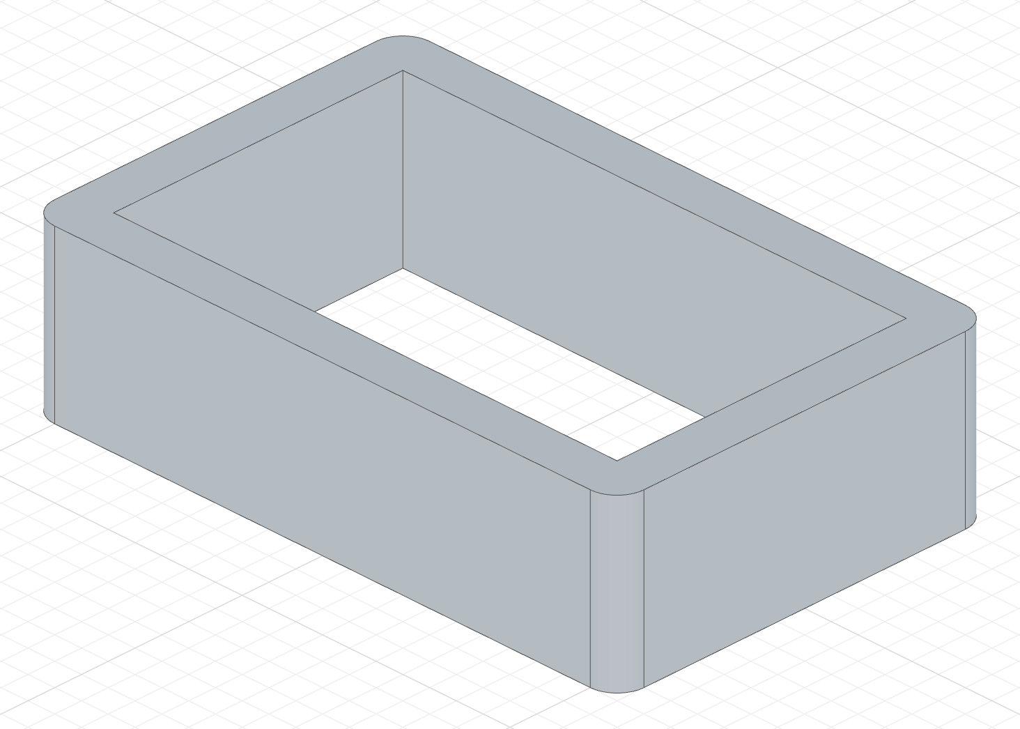
Two-direction offset
Pass two values to offset in both directions. The second offset automatically goes in the opposite direction of the first:
The code behind it
import { sketch, extrude } from 'fluidcad/core';
import { line } from 'fluidcad/core';
import { coincident, distance, fix, horizontal, vertical } from "fluidcad/constraints";

sketch("xy", () => {
    const sg1 = line([-50, -30], [50, -30]);
    const sg2 = line([50, -30], [50, 30]);
    const sg3 = line([50, 30], [-50, 30]);
    const sg4 = line([-50, 30], [-50, -30]);
    coincident(sg1.end(), sg2.start());
    coincident(sg2.end(), sg3.start());
    coincident(sg3.end(), sg4.start());
    coincident(sg4.end(), sg1.start());
    horizontal(sg1);
    vertical(sg2);
    horizontal(sg3);
    vertical(sg4);
    fix(sg1.start(), [-50, -30]);
    distance(sg1.start(), sg1.end(), 100);
    distance(sg2.start(), sg2.end(), 60);
  })

extrude(30).thin(5, -3)
Open profiles
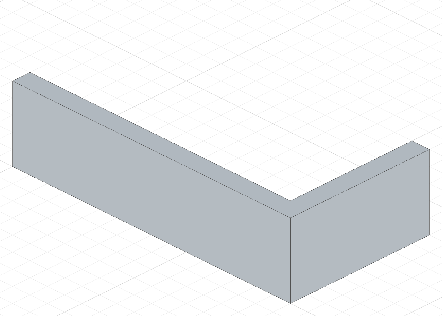
Thin extrude also works with open profiles (unclosed curves). The ends are capped with straight lines:
The code behind it
import { sketch, extrude } from 'fluidcad/core';
import { line } from 'fluidcad/core';
import { coincident, horizontal, vertical } from "fluidcad/constraints";

sketch("xy", () => {
    const sg1 = line([0, 0], [80, 0]);
    const sg2 = line([80, 0], [80, 40]);
    horizontal(sg1);
    coincident(sg1.end(), sg2.start());
    vertical(sg2);
  })

extrude(20).thin(5).new()
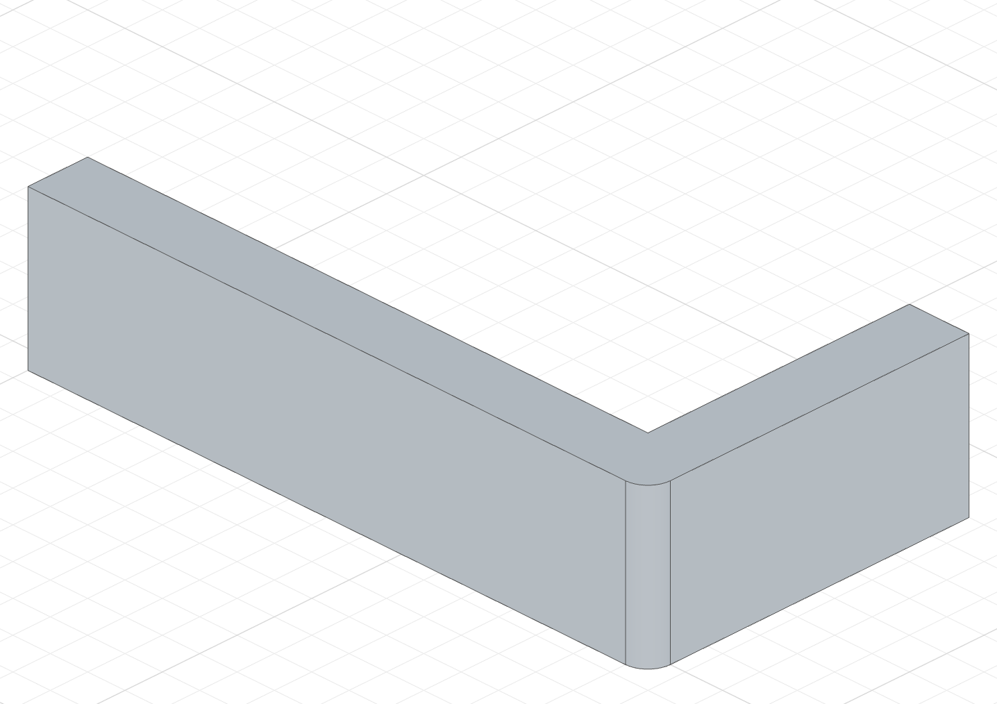
Two-direction offset works with open profiles as well — the original curve is not used, only the two offset curves:
The code behind it
import { sketch, extrude } from 'fluidcad/core';
import { line } from 'fluidcad/core';
import { coincident, horizontal, vertical } from "fluidcad/constraints";

sketch("xy", () => {
    const sg1 = line([0, 0], [80, 0]);
    const sg2 = line([80, 0], [80, 40]);
    horizontal(sg1);
    coincident(sg1.end(), sg2.start());
    vertical(sg2);
  })

extrude(20).thin(5, -3).new()
Thin extrude works with all extrude modes — symmetric, draft, remove, two distances, and face targets.
Region picking
A sketch with overlapping shapes contains several closed regions. By default the extrusion takes all of them, with nested shapes as holes (the Drill holes toggle). To extrude particular regions, pick them from the dialog. The same works on cut, revolve, sweep and wrap.
Picking in the viewport
- Open the extrude dialog (or double-click an existing extrude in the timeline to edit it) and choose the sketch.
- Click Pick regions under the Sketch picker. Every region of the sketch shows in the viewport as a face you can click, and the ghost preview follows your picks.
- Click a region to add it; click a selected region again to remove it. The picker counts the picks (2 regions) and its ✕ clears them all.
- Done leaves the mode; the picks stay. Apply declares each picked region inside the sketch with
region()and names them on the extrude with.region(...)— with nothing picked the extrude takes every region and nothing is written.
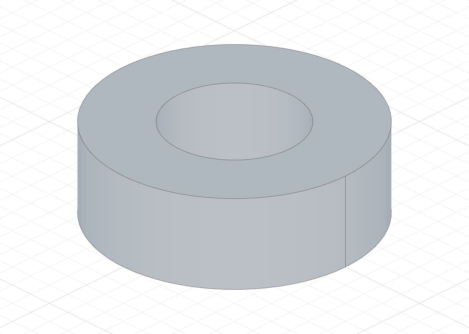
Two concentric circles make two regions: the ring, and the disc inside the inner circle. Picking the ring writes a region('r1', outer) declaration into the sketch and extrude(20, s).region('r1'):
The code behind it
The declaration lists the ring's outer loop: the circle outer, passed as the variable itself. Nothing in it says how big the ring is, so resizing either circle leaves the pick intact.
import { sketch, circle, region, extrude } from 'fluidcad/core';

const s = sketch("xy", () => {
    const outer = circle([0, 0], 60);
    const inner = circle([0, 0], 30);
    region('r1', outer);         // written by the pick: the ring, whose outer loop is `outer`
})

extrude(20, s).region('r1')
Reading a declaration
region(name, ...entities) sits inside the sketch callback and names a region by the sketch entities on its outer loop — the variables themselves, not their names in a string, so the editor checks them and renames them with the rest of the file:
region('ring', outer)— the region whose outer loop is the circleouter. Holes never take part: the ring's declaration does not mentioninner, and cutting a hole into a region later does not change it. The hole is a region of its own,region('disc', inner).region('plate', b, r, t, l)— the region closed by the four linesb,r,tandl. The order carries no meaning.region('crescent', c1, far(c2))—far()marks an entity the region lies on the far side of: on the right of the edge's own direction. A circle runs counter-clockwise, sofar(c2)puts the region outsidec2, and this is the crescent insidec1and outsidec2.region('lens', c1, c2)is the lens inside both. The picker writesfar()wherever it applies; you never work it out yourself.region('corner', r.top(), r.right(), far(l))— one edge of a multi-edge statement: the top and right edges of therect()r. A barerstands for every edge ofron the region, soregion('inside', r)names the inside of a rectangle without spelling out its sides. Projected edges readp.ref(2), offset edgeso.edge(0).
The extrude names the regions it takes: extrude(20, s).region('lens', 'crescent'). The picker reuses a declaration that already lists the region it clicked and allocates r1, r2, … for the rest; rename them in the source if you like, in both places.
A declaration holds no coordinates, so a dimension change never moves a region away from it. It also survives an unrelated entity being added or deleted, and a hole being cut into the region. Deleting an entity it names is a compile error at the declaration, and the sketcher's Delete key drops the entity from the declaration for you.
When the region's own boundary changes — a line drawn across it, a bounding entity redrawn — the feature takes the region that keeps most of the declared boundary, as long as the match is clear. If it is not, the feature reports an error that lists the nearest regions in the same far() form. Pick the region again, or paste the right boundary into the declaration.
No-argument extrude
extrude() // uses a default distance of 25
With no argument the extrusion takes a default distance, and the ghost in the viewport can be dragged to set it.
Accessing geometry
const e = extrude(30)

e.endFaces()       // top face(s)
e.startFaces()     // bottom face(s)
e.sideFaces()      // side face(s)
e.endEdges()       // edges on the top
e.startEdges()     // edges on the bottom
e.sideEdges()      // edges on the sides
e.internalEdges()  // edges created inside (from fusion)
e.internalFaces()  // faces created inside (from fusion)
e.capFaces()       // cap faces of a thin extrude from an open profile
e.capEdges()       // edges on those caps

const c = cut(15)

c.startEdges()         // edges at the top of the cut
c.endEdges()           // edges at the bottom of the cut
c.internalEdges()      // edges created inside the solid
c.internalFaces()      // faces inside the cut pocket
Fusion scope
extrude(30).add()              // fuse with all touching solids (default)
extrude(30).new()              // create a separate solid, don't fuse
extrude(30).remove()           // subtract from all intersecting solids — same as cut(30)
cut(30).scope(box)             // subtract only from `box`