Loft
Loft blends two or more sketch profiles on different planes into one smooth solid. Reach for it when the cross-section changes along the length — a vase, a duct that goes from rectangular to round, a hopper.
In the viewport
- Sketch each section on its own plane (a standard plane, an offset plane, or a face). Click Loft on the toolbar.
- Click each profile in the timeline or the viewport. They stack up in the Sketches slot in the order you pick them, and that order is the order the surface passes through them — drag the chips to change it.
- Click Apply.
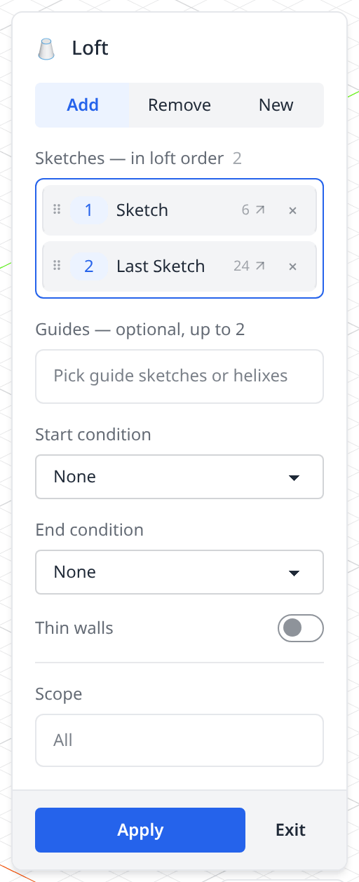
- 1Add / Remove / NewWhat the lofted solid does to the model — fuse, cut, or stand alone. See Add, New and Remove below.
- 2Sketches — in loft orderTwo or more sections, numbered in pick order. The surface runs through them in that order, so a wrong order gives a twisted or self-crossing solid; drag a chip by its handle to reorder.
- 3GuidesUp to two open curves the surface must follow along its sides. Each guide has to pass through every profile. Optional — see Guide curves below.
- 4Start conditionHow the surface leaves the first profile: None, Normal (perpendicular to the profile plane) or Tangent (bulging out inside the plane), with a magnitude.
- 5End conditionThe same for the last profile. The two ends are set independently.
- 6Thin wallsLofts a wall of the thickness you type instead of a filled solid. Cannot be combined with guides.
- 7ScopeWhich solids the Add or Remove applies to.
- 8ApplyWrites the statement and adds the timeline row; Exit writes nothing.
From sections to a solid
A vase is four circles on planes 40 apart, each a different diameter. Loft passes one surface through all of them:
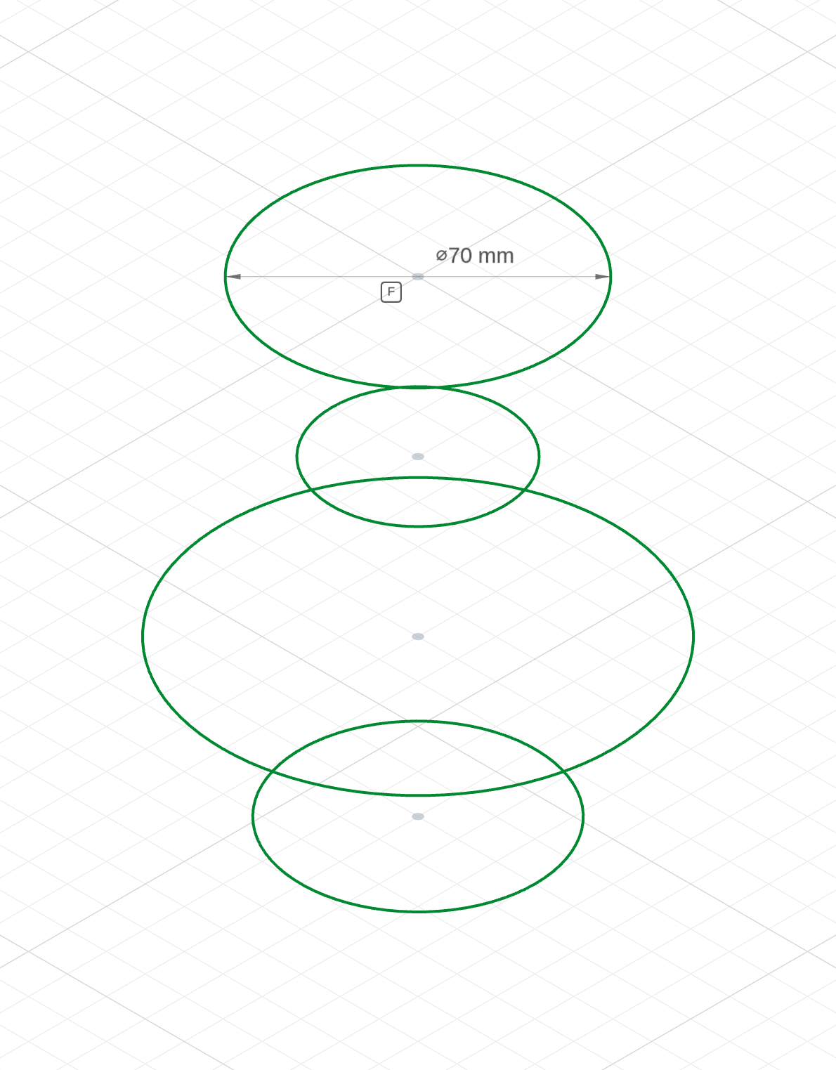
four sectionsThe sections, bottom to top: a Ø60 foot on the ground plane, a Ø100 belly at 40, a Ø44 neck at 80 and a Ø70 lip at 120. Nothing is solid yet.
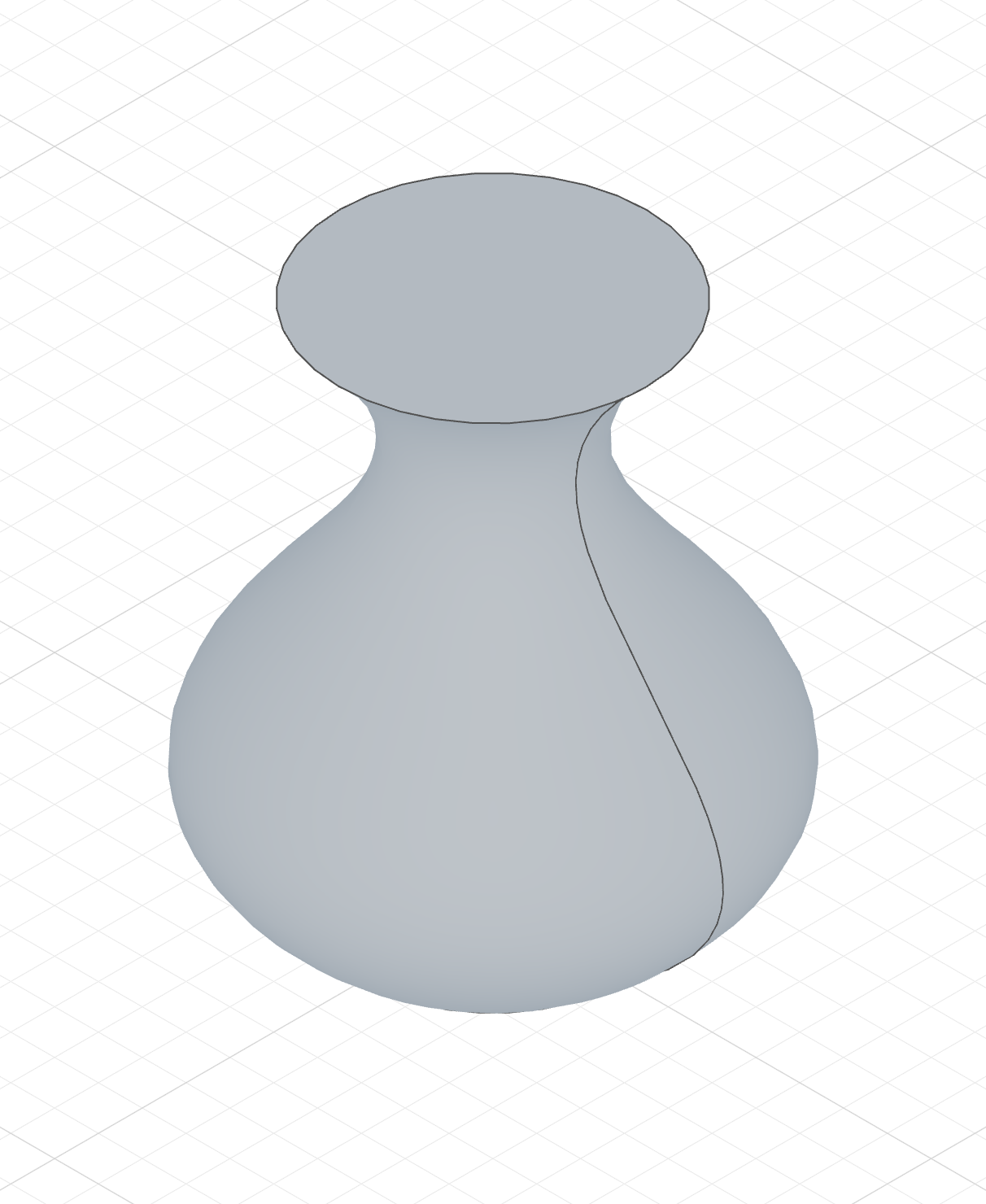
loft(foot, belly, neck, lip)One solid whose section follows the circles — out to the belly, in at the neck, out again at the lip.
The four sketches
import { sketch, plane, circle } from 'fluidcad/core';
import { diameter, fix } from "fluidcad/constraints";

// Nothing solid yet — four round sections on planes 40 apart, each fully constrained. Only the
// diameter changes from one to the next: a Ø60 foot, a Ø100 belly, a Ø44 neck
// and a Ø70 lip.
const foot = sketch("xy", () => {
    const c = circle([0, 0], 60);
    fix(c.center(), [0, 0]);
    diameter(c, 60);
  })

const belly = sketch(plane("xy", { offset: 40 }), () => {
    const c = circle([0, 0], 100);
    fix(c.center(), [0, 0]);
    diameter(c, 100);
  })

const neck = sketch(plane("xy", { offset: 80 }), () => {
    const c = circle([0, 0], 44);
    fix(c.center(), [0, 0]);
    diameter(c, 44);
  })

const lip = sketch(plane("xy", { offset: 120 }), () => {
    const c = circle([0, 0], 70);
    fix(c.center(), [0, 0]);
    diameter(c, 70);
  })
The complete file
The sketches go into loft() in the order the surface should pass through them — the same order the chips take in the Sketches slot.
import { sketch, plane, loft, circle } from 'fluidcad/core';
import { diameter, fix } from "fluidcad/constraints";

// Four round sections on planes 40 apart, each fully constrained. Only the
// diameter changes from one to the next: a Ø60 foot, a Ø100 belly, a Ø44 neck
// and a Ø70 lip.
const foot = sketch("xy", () => {
    const c = circle([0, 0], 60);
    fix(c.center(), [0, 0]);
    diameter(c, 60);
  })

const belly = sketch(plane("xy", { offset: 40 }), () => {
    const c = circle([0, 0], 100);
    fix(c.center(), [0, 0]);
    diameter(c, 100);
  })

const neck = sketch(plane("xy", { offset: 80 }), () => {
    const c = circle([0, 0], 44);
    fix(c.center(), [0, 0]);
    diameter(c, 44);
  })

const lip = sketch(plane("xy", { offset: 120 }), () => {
    const c = circle([0, 0], 70);
    fix(c.center(), [0, 0]);
    diameter(c, 70);
  })

// The surface passes through the four sections in the order they are listed,
// swelling out to the belly, pinching in at the neck and flaring at the lip.
loft(foot, belly, neck, lip);
Multiple profiles
Every sketch in the list is a section the surface has to pass through, so adding a section is how you shape the result. The same vase built up one section at a time:
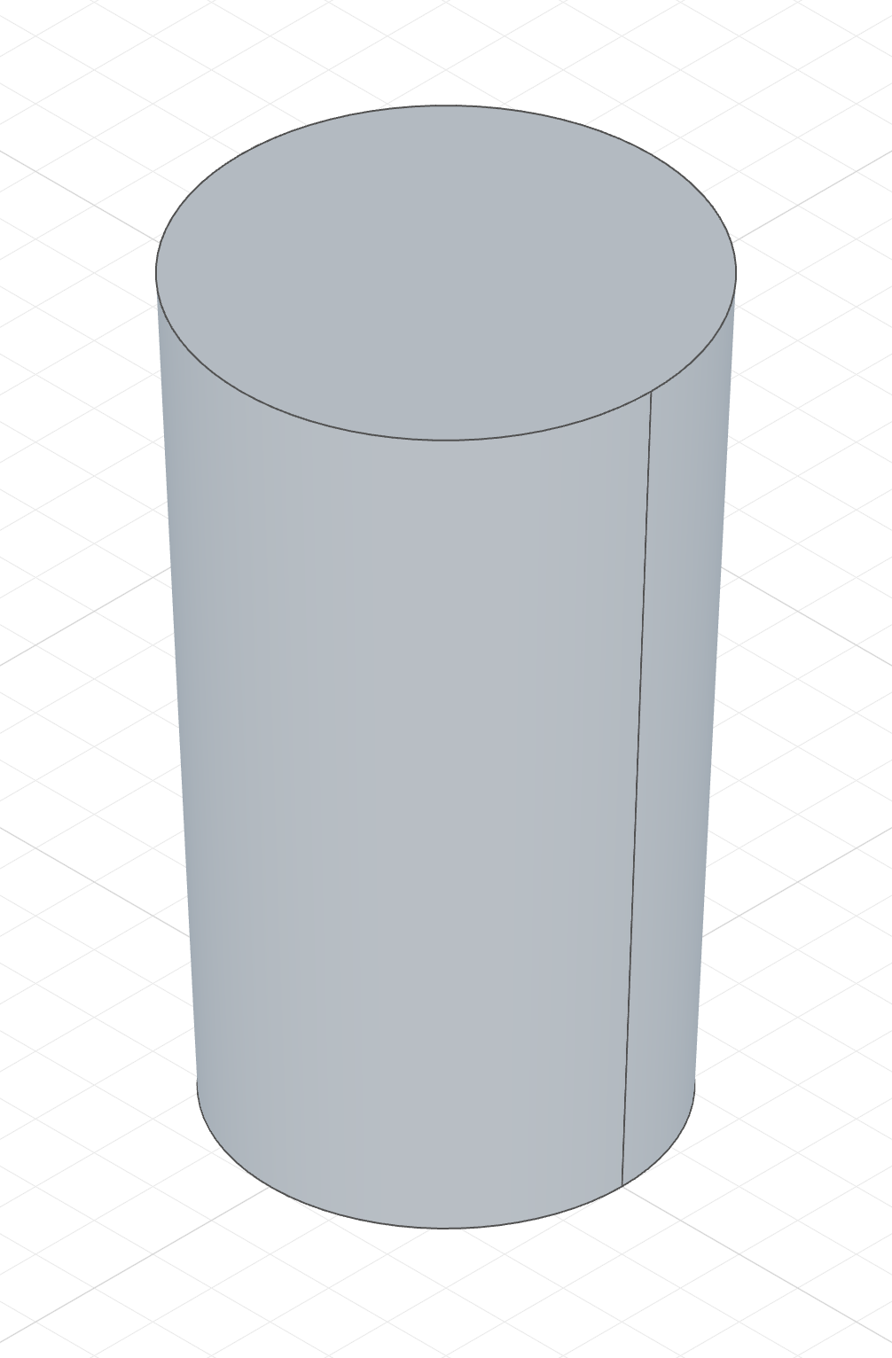
loft(foot, lip)Foot and lip only. The surface runs straight between them — a tube tapering gently from Ø60 to Ø70.
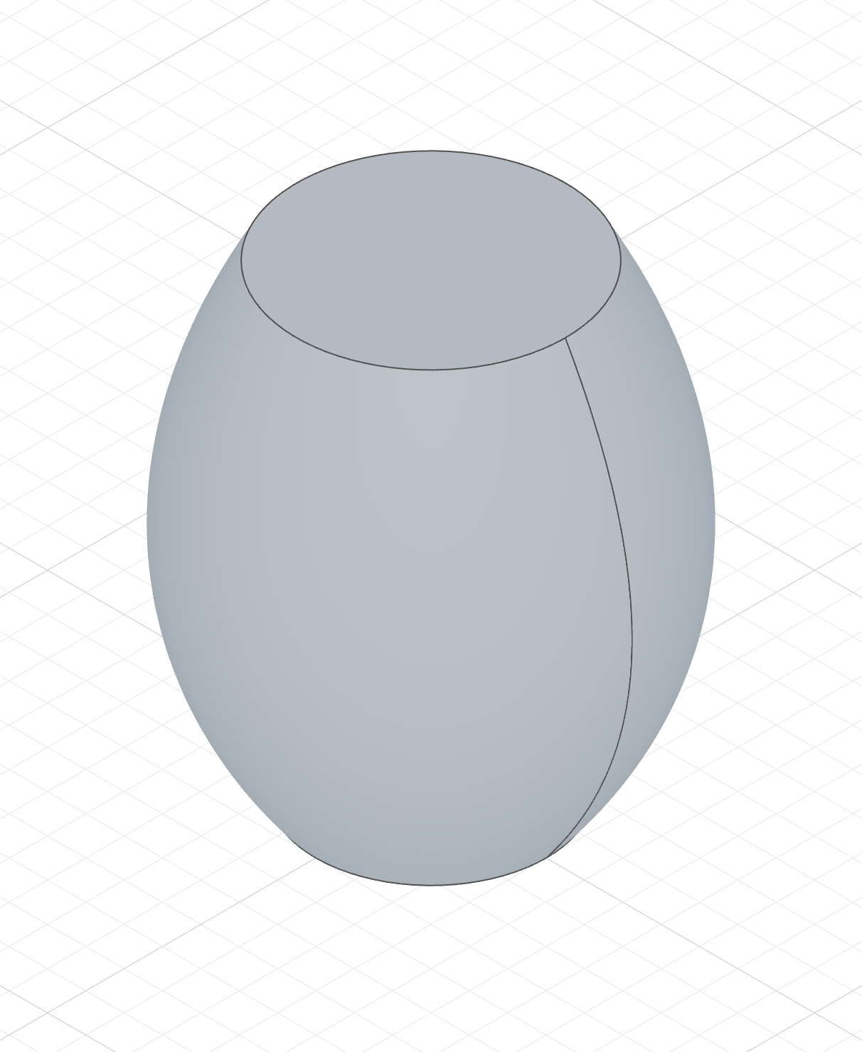
loft(foot, belly, lip)The Ø100 belly added in the middle. The surface has to pass through it on the way up, so the tube swells out.
loft(foot, belly, neck, lip)The Ø44 neck between belly and lip pinches it back in — the vase.
The three-section column's code
Each column's file contains only the sketches it lofts; the highlighted line is the only difference in what loft() is handed.
import { sketch, plane, loft, circle } from 'fluidcad/core';
import { diameter, fix } from "fluidcad/constraints";

// The foot and lip again, with the Ø100 belly between them.
const foot = sketch("xy", () => {
    const c = circle([0, 0], 60);
    fix(c.center(), [0, 0]);
    diameter(c, 60);
  })

const belly = sketch(plane("xy", { offset: 40 }), () => {
    const c = circle([0, 0], 100);
    fix(c.center(), [0, 0]);
    diameter(c, 100);
  })

const lip = sketch(plane("xy", { offset: 120 }), () => {
    const c = circle([0, 0], 70);
    fix(c.center(), [0, 0]);
    diameter(c, 70);
  })

// Three sections: the surface now has to pass through the belly on its way
// up, so the tube swells out in the middle.
loft(foot, belly, lip);
The profiles must be on different planes — typically parallel planes at different offsets — and the order in the list matters: a belly listed after the neck would make the surface double back on itself.
Guide curves
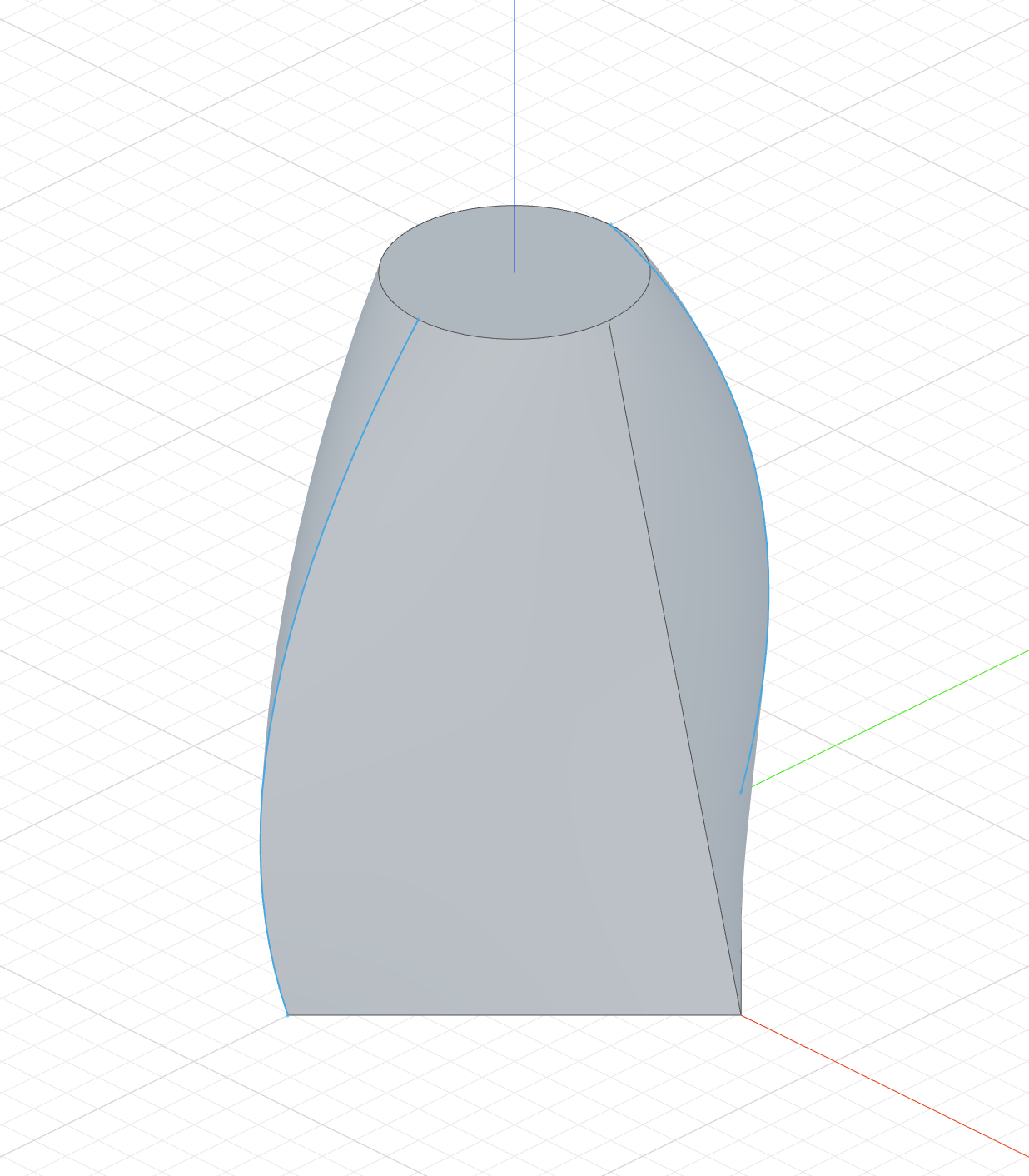
Guides are side rails the transition surface must follow. Pass one or two open curves; each guide has to pass through every profile. A single sketch may carry several guide curves (for example a curve and its mirror()) — each connected curve counts as one guide:
The code behind it
import { sketch, plane, loft, line, circle, bezier, mirror, yAxis } from 'fluidcad/core';
import { coincident, equal, perpendicular, fix } from 'fluidcad/constraints';

const p1 = sketch("top", () => {
    // A square rotated 45°, 50 across the flats
    const s1 = line([35.355339, 0], [0, 35.355339]);
    const s2 = line([0, 35.355339], [-35.355339, 0]);
    const s3 = line([-35.355339, 0], [0, -35.355339]);
    const s4 = line([0, -35.355339], [35.355339, 0]);
    coincident(s1.end(), s2.start());
    coincident(s2.end(), s3.start());
    coincident(s3.end(), s4.start());
    coincident(s4.end(), s1.start());
    equal(s1, s2);
    equal(s2, s3);
    equal(s3, s4);
    perpendicular(s1, s2);
    fix(s1.start());
  })

const p2 = sketch(plane("top", 80), () => {
    circle([0, 0], 30);
  })

// One sketch, two rails: the bezier and its mirror each count as one guide
const g1 = sketch("right", () => {
    bezier([Math.sqrt(2) * 25, 0], [50, 40], [15, 80])
    mirror(yAxis())
})

loft(p1, p2).guides(g1)
Here the bezier and its mirror form two rails; the square's corners ride them all the way up to the circle. Guides can also be passed as separate arguments:
loft(p1, p2).guides(rightRail, leftRail)
Guides compose with start/end conditions: the condition fades out around each guide's contact point, so the rails keep their sides of the surface while the condition shapes the rest. Guides cannot be combined with thin walls.
loft(p1, p2).guides(g1).startCondition('normal')
Vertex connections from code
Use .connect(...) to choose which profile corners belong together. Pass one
point per profile, in the same order as the loft() arguments, and repeat the
call for each connection. Each connection becomes an edge of the loft; the side
faces split along it.
This example builds the outer solid of a square-to-round duct transition. The
round section uses four arcs so it has vertices, and the connections hold the
twist at the named twistDegrees value:
The code behind it
import { sketch, plane, line, arc, loft } from 'fluidcad/core';
import { fix, radius } from 'fluidcad/constraints';

const squareWidth = 80;
const roundRadius = 30;
const transitionLength = 100;
const twistDegrees = 20;
const halfWidth = squareWidth / 2;

const square = sketch('xy', () => {
  const bottom = line([-halfWidth, -halfWidth], [halfWidth, -halfWidth]);
  const right = line([halfWidth, -halfWidth], [halfWidth, halfWidth]);
  const top = line([halfWidth, halfWidth], [-halfWidth, halfWidth]);
  const left = line([-halfWidth, halfWidth], [-halfWidth, -halfWidth]);
  // The named dimensions above drive these fixed endpoints.
  for (const side of [bottom, right, top, left]) {
    fix(side.start());
    fix(side.end());
  }
  return { bottom, right, top, left };
});

const round = sketch(plane('xy', { offset: transitionLength }), () => {
  const corners = [-135, -45, 45, 135].map(degrees => {
    const angle = (degrees + twistDegrees) * Math.PI / 180;
    return [roundRadius * Math.cos(angle), roundRadius * Math.sin(angle)];
  });
  // Four arcs give the round end four real junction vertices.
  const bottom = arc(corners[0], corners[1], [0, 0]);
  const right = arc(corners[1], corners[2], [0, 0]);
  const top = arc(corners[2], corners[3], [0, 0]);
  const left = arc(corners[3], corners[0], [0, 0]);
  for (const side of [bottom, right, top, left]) {
    fix(side.start());
    fix(side.end());
    radius(side, roundRadius);
  }
  return { bottom, right, top, left };
});

// The outer solid of a square-to-round duct transition.
loft(square, round)
  .connect(square.geometries.bottom.start(), round.geometries.bottom.start())
  .connect(square.geometries.right.start(), round.geometries.right.start())
  .connect(square.geometries.top.start(), round.geometries.top.start())
  .connect(square.geometries.left.start(), round.geometries.left.start());
Returning geometry from a sketch callback makes it available through
sketch.geometries. Point references follow their sketch planes, so the same
code works on offset or tilted planes. You can also connect world coordinates
such as [0, 0, 40] or solid-edge endpoints such as e.endEdges(0).start().
A vertex of an offset() result is named by edge index,
a.geometries.o.edge(2).start() — see
naming offset edges
for the index rule and why a sign flip shifts the indices.
To use a point of a select(...), declare the selection on its own line before
the loft: const tip = select(edge().farthest('x'));, then
.connect(tip.end(), ...). A selection written inside .connect(...) runs
after loft(...) and the loft reports an error.
Connections require closed, planar profiles with one region each. Points must be vertices: split a full circle or ellipse into arcs first. Connections compose with start/end conditions, guides and thin walls. A guide may ride a connected vertex; a guide that crosses a connection between two profiles is reported as an error. With thin walls each connection is carried onto both walls — the sharp offset corner on one side and the crest of the rounded corner on the other, where an edge runs along the rounding. Thin walls merge smooth junctions into one edge, so a thin loft connects real profile corners only, not the arc ends of a split circle.
Start and end conditions
The condition rows control how the surface leaves the first profile and arrives at the last one:
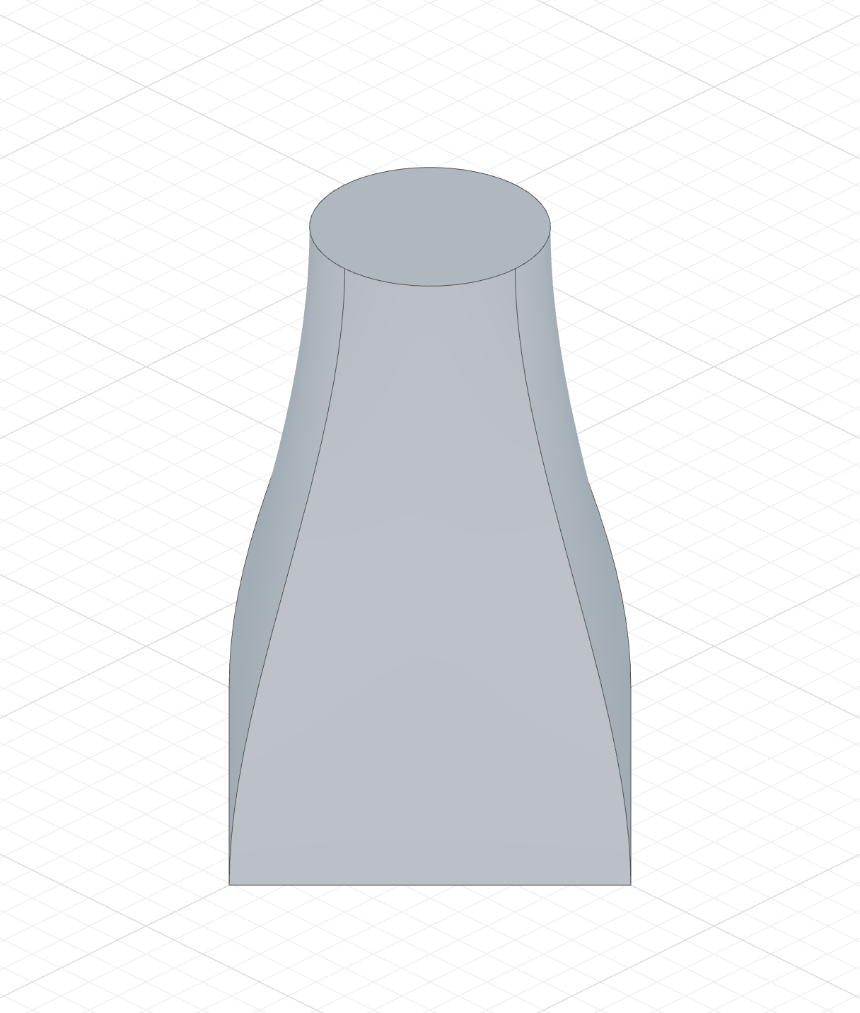
'none'— no constraint (default)'normal'— the surface takes off perpendicular to the profile plane'tangent'— the surface takes off inside the profile plane, bulging outward
The code behind it
import { sketch, plane, loft, line, circle } from 'fluidcad/core';
import { coincident, equal, perpendicular, fix } from 'fluidcad/constraints';

const p1 = sketch("top", () => {
    // A square rotated 45°, 50 across the flats
    const s1 = line([35.355339, 0], [0, 35.355339]);
    const s2 = line([0, 35.355339], [-35.355339, 0]);
    const s3 = line([-35.355339, 0], [0, -35.355339]);
    const s4 = line([0, -35.355339], [35.355339, 0]);
    coincident(s1.end(), s2.start());
    coincident(s2.end(), s3.start());
    coincident(s3.end(), s4.start());
    coincident(s4.end(), s1.start());
    equal(s1, s2);
    equal(s2, s3);
    equal(s3, s4);
    perpendicular(s1, s2);
    fix(s1.start());
  })

const p2 = sketch(plane("top", 80), () => {
    circle([0, 0], 30);
  })

// The surface leaves the square and arrives at the circle perpendicular
// to their planes, swelling the transition outward
loft(p1, p2)
    .startCondition('normal', 1)
    .endCondition('normal', 1)
The magnitude scales the takeoff strength (default 1). Negative values flip the direction — a 'tangent' condition with a negative magnitude pinches inward instead of bulging:
loft(p1, p2).startCondition('normal', 2)     // stronger perpendicular takeoff
loft(p1, p2).endCondition('tangent', -0.5)   // gentle inward pinch at the top
loft(p1, p2).startCondition('normal')        // conditions can differ per end
          .endCondition('tangent')
Conditions require closed profiles and work with thin walls (both walls follow the condition).
Add, New and Remove
A tank lid, and one loft from a Ø44 circle on a plane halfway through the lid to a 16 × 16 square 50 up. Only the tab changes:
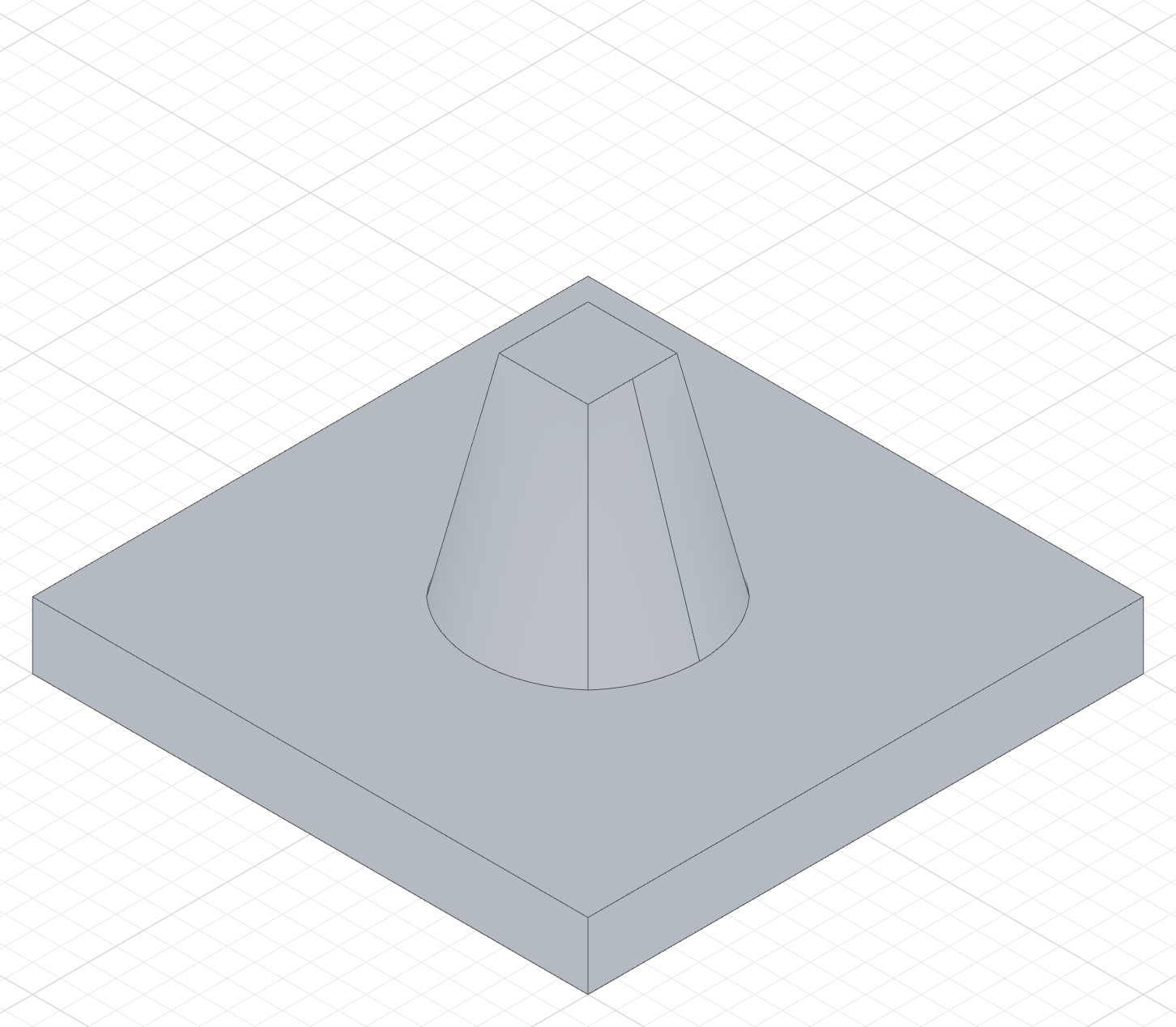
loft(s1, s2)The loft fuses with the lid — a round-to-square nozzle grows out of it.
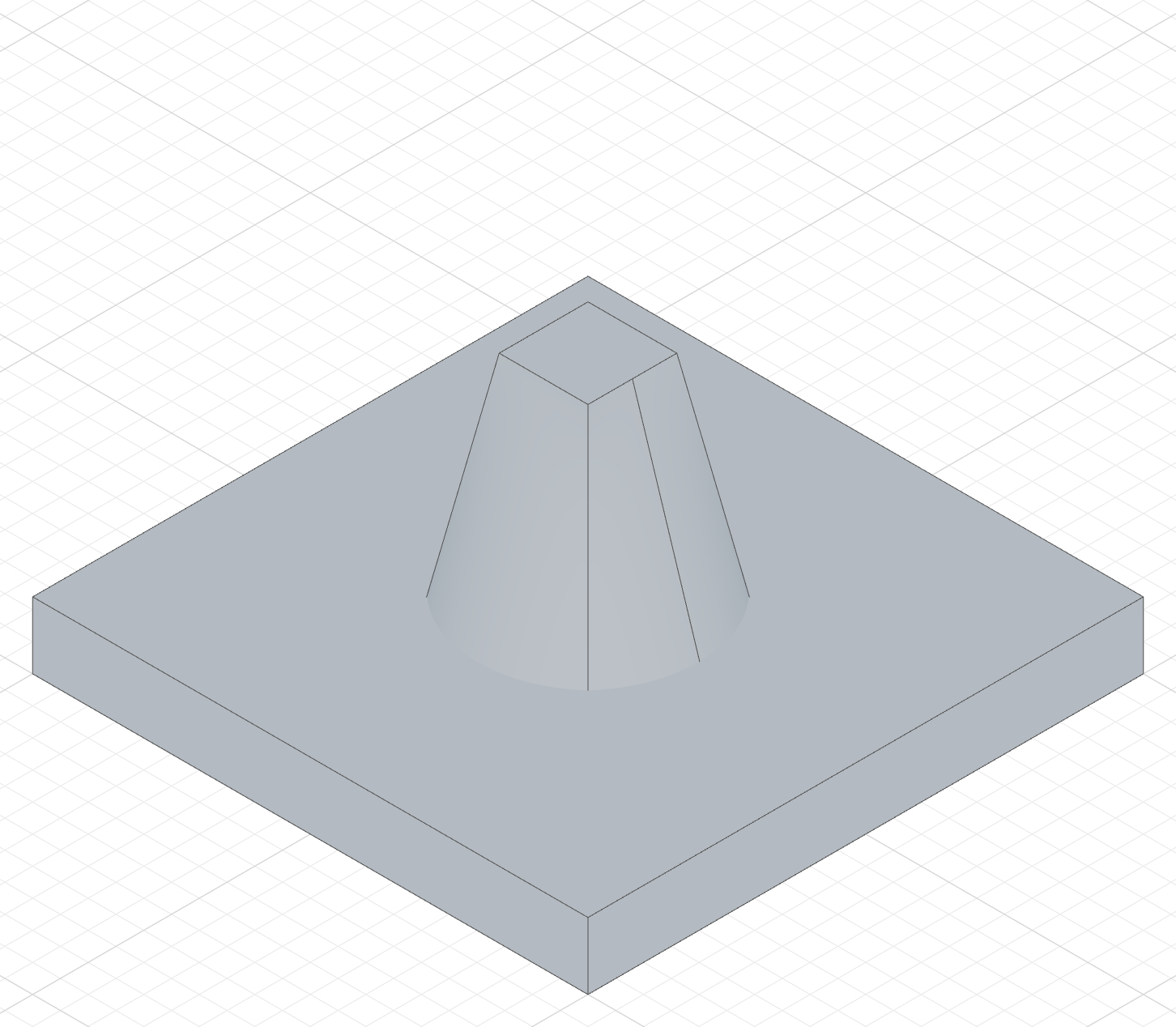
loft(s1, s2).new()The nozzle is a separate solid seated in the lid.
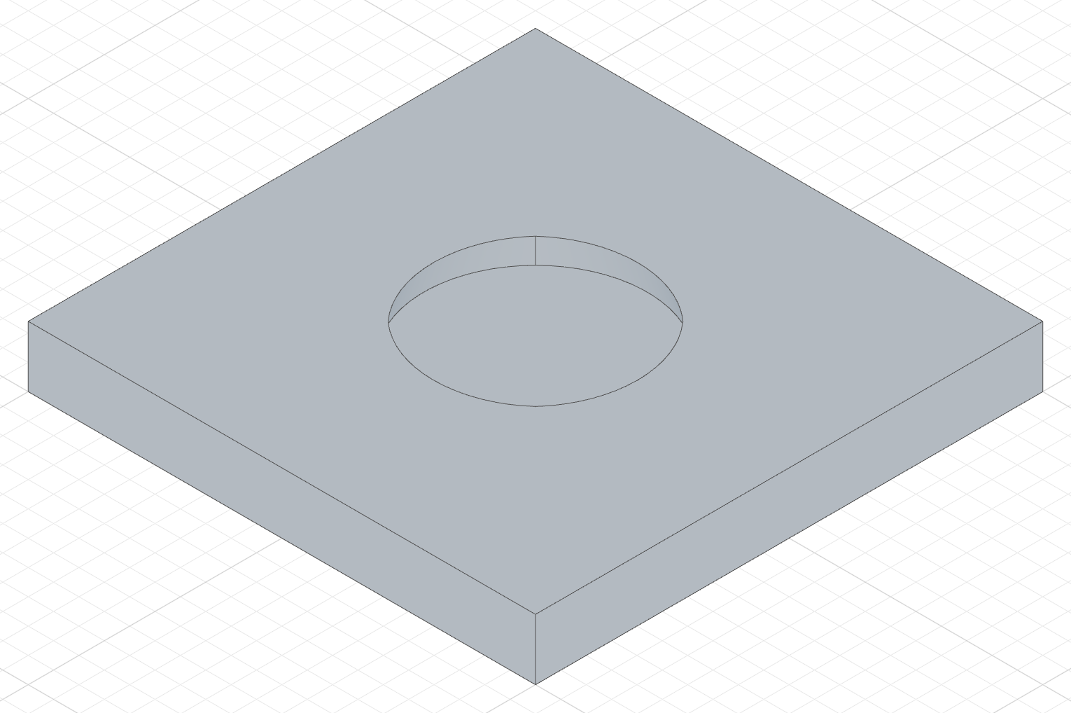
loft(s1, s2).remove()The nozzle's volume is cut out — a funnel-shaped recess down to the first profile.
The Add column's code
The New and Remove columns only change the highlighted line.
import { sketch, extrude, loft, plane, circle, line } from 'fluidcad/core';
import { coincident, distance, fix, horizontal, vertical } from "fluidcad/constraints";

// The base part every column shares: a 100 x 100 x 12 tank lid.
sketch("xy", () => {
    const sg1 = line([-50, -50], [50, -50]);
    const sg2 = line([50, -50], [50, 50]);
    const sg3 = line([50, 50], [-50, 50]);
    const sg4 = line([-50, 50], [-50, -50]);
    coincident(sg1.end(), sg2.start());
    coincident(sg2.end(), sg3.start());
    coincident(sg3.end(), sg4.start());
    coincident(sg4.end(), sg1.start());
    horizontal(sg1);
    vertical(sg2);
    horizontal(sg3);
    vertical(sg4);
    fix(sg1.start(), [-50, -50]);
    distance(sg1.start(), sg1.end(), 100);
    distance(sg2.start(), sg2.end(), 100);
  })
const lid = extrude(12)

// First profile: a Ø44 circle on a plane halfway through the lid (6 up).
const s1 = sketch(plane("xy", { offset: 6 }), () => {
    circle([0, 0], 44);
  })

// Second profile: a 16 x 16 square outlet, 50 up.
const s2 = sketch(plane("xy", { offset: 50 }), () => {
    const t1 = line([-8, -8], [8, -8]);
    const t2 = line([8, -8], [8, 8]);
    const t3 = line([8, 8], [-8, 8]);
    const t4 = line([-8, 8], [-8, -8]);
    coincident(t1.end(), t2.start());
    coincident(t2.end(), t3.start());
    coincident(t3.end(), t4.start());
    coincident(t4.end(), t1.start());
    horizontal(t1);
    vertical(t2);
    horizontal(t3);
    vertical(t4);
    fix(t1.start(), [-8, -8]);
    distance(t1.start(), t1.end(), 16);
    distance(t2.start(), t2.end(), 16);
  })

// Add tab: the loft fuses with the lid — a round-to-square nozzle grows out of it.
loft(s1, s2)
Thin walls
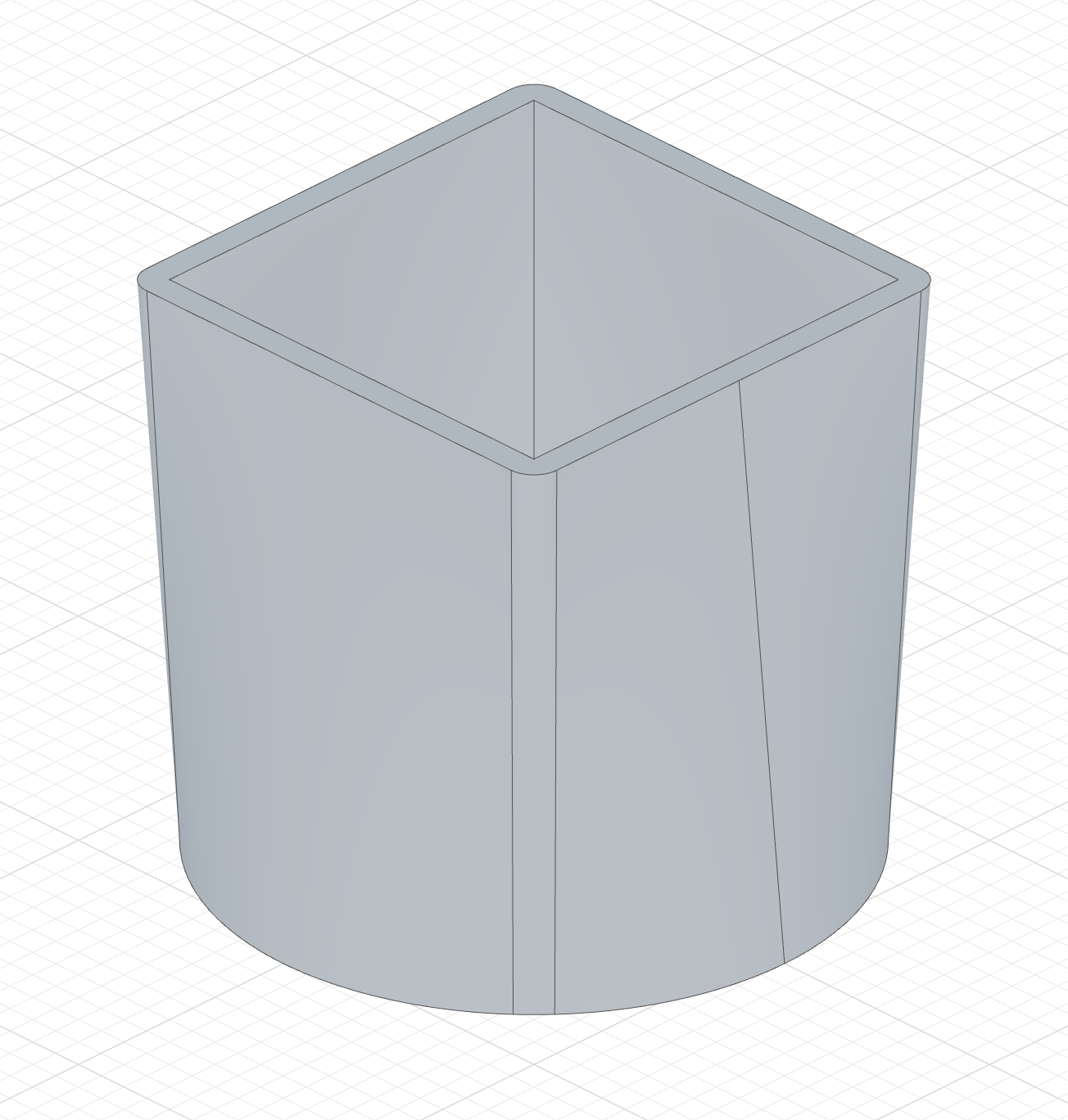
Turn on Thin to offset every profile's edges by the thickness and loft the bands — a shell instead of a filled loft:
The code behind it
import { sketch, loft, plane } from 'fluidcad/core';
import { circle, line } from 'fluidcad/core';
import { coincident, distance, fix, horizontal, vertical } from "fluidcad/constraints";

const s1 = sketch("xy", () => {
    circle([0, 0], 100);
  })

const s2 = sketch(plane("xy", { offset: 100 }), () => {
    const sg1 = line([-40, -40], [40, -40]);
    const sg2 = line([40, -40], [40, 40]);
    const sg3 = line([40, 40], [-40, 40]);
    const sg4 = line([-40, 40], [-40, -40]);
    coincident(sg1.end(), sg2.start());
    coincident(sg2.end(), sg3.start());
    coincident(sg3.end(), sg4.start());
    coincident(sg4.end(), sg1.start());
    horizontal(sg1);
    vertical(sg2);
    horizontal(sg3);
    vertical(sg4);
    fix(sg1.start(), [-40, -40]);
    distance(sg1.start(), sg1.end(), 80);
    distance(sg2.start(), sg2.end(), 80);
  })

loft(s1, s2).thin(5)
loft(s1, s2).thin(5)     // 5 units outward
loft(s1, s2).thin(-5)    // 5 units inward
loft(s1, s2).thin(5, -3) // dual offset
All profiles must be sketches with matching topology (same number of wires).
Thin in the three modes
The same loft with Thin on and a wall of 2:
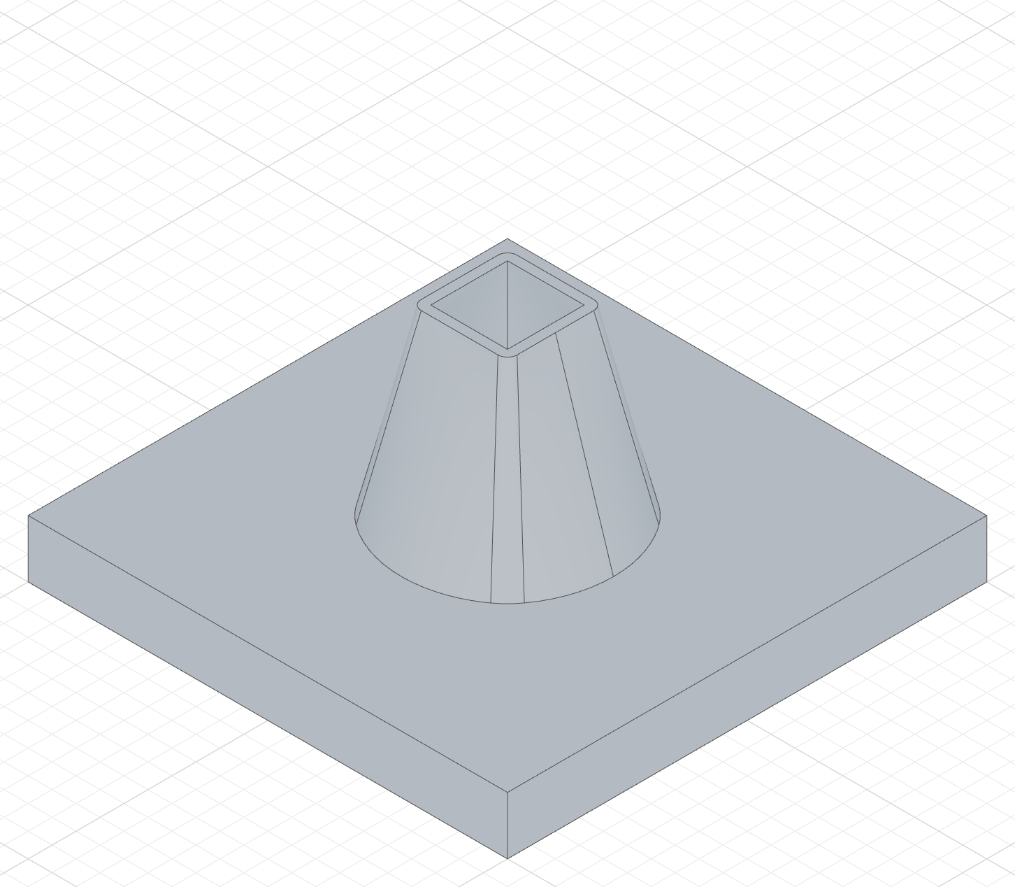
loft(s1, s2).thin(2)A 2-thick hopper wall fused with the lid.
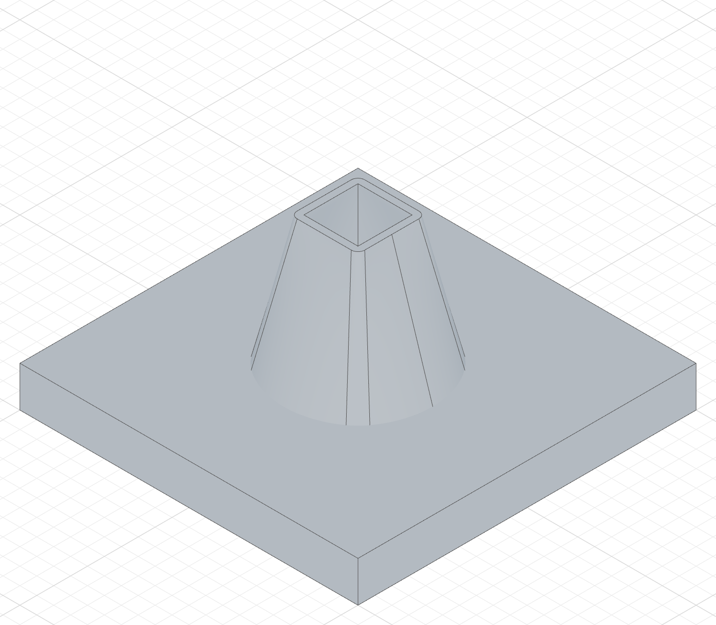
loft(s1, s2).thin(2).new()The hopper wall as a separate body.
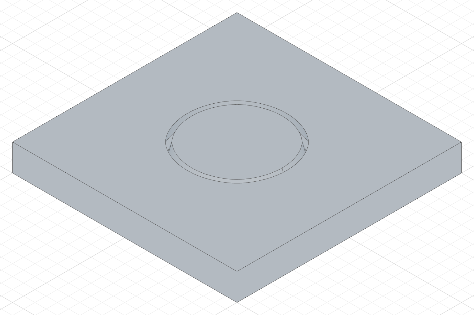
loft(s1, s2).thin(2).remove()Only the wall is cut — a tapered ring slot in the lid.
The Add column's code
import { sketch, extrude, loft, plane, circle, line } from 'fluidcad/core';
import { coincident, distance, fix, horizontal, vertical } from "fluidcad/constraints";

// The base part every column shares: a 100 x 100 x 12 tank lid.
sketch("xy", () => {
    const sg1 = line([-50, -50], [50, -50]);
    const sg2 = line([50, -50], [50, 50]);
    const sg3 = line([50, 50], [-50, 50]);
    const sg4 = line([-50, 50], [-50, -50]);
    coincident(sg1.end(), sg2.start());
    coincident(sg2.end(), sg3.start());
    coincident(sg3.end(), sg4.start());
    coincident(sg4.end(), sg1.start());
    horizontal(sg1);
    vertical(sg2);
    horizontal(sg3);
    vertical(sg4);
    fix(sg1.start(), [-50, -50]);
    distance(sg1.start(), sg1.end(), 100);
    distance(sg2.start(), sg2.end(), 100);
  })
const lid = extrude(12)

// First profile: a Ø44 circle on a plane halfway through the lid (6 up).
const s1 = sketch(plane("xy", { offset: 6 }), () => {
    circle([0, 0], 44);
  })

// Second profile: a 16 x 16 square outlet, 50 up.
const s2 = sketch(plane("xy", { offset: 50 }), () => {
    const t1 = line([-8, -8], [8, -8]);
    const t2 = line([8, -8], [8, 8]);
    const t3 = line([8, 8], [-8, 8]);
    const t4 = line([-8, 8], [-8, -8]);
    coincident(t1.end(), t2.start());
    coincident(t2.end(), t3.start());
    coincident(t3.end(), t4.start());
    coincident(t4.end(), t1.start());
    horizontal(t1);
    vertical(t2);
    horizontal(t3);
    vertical(t4);
    fix(t1.start(), [-8, -8]);
    distance(t1.start(), t1.end(), 16);
    distance(t2.start(), t2.end(), 16);
  })

// Add + Thin: a 2-thick hopper wall instead of a solid nozzle, fused with the lid.
loft(s1, s2).thin(2)
Accessing geometry
const l = loft(s1, s2)

l.endFaces()       // face at the last profile
l.startFaces()     // face at the first profile
l.sideFaces()      // the transition surface(s)
l.endEdges()       // edges at the last profile
l.startEdges()     // edges at the first profile
l.sideEdges()      // edges along the sides
l.internalFaces()  // inner wall face(s) of a thin loft (closed profiles)
l.capFaces()       // cap face(s) of a thin loft (open profiles)
Fusion scope
loft(s1, s2).new()                // create a separate solid
loft(s1, s2).add()                // fuse with touching solids (default)
loft(s1, s2).remove()             // subtract from all intersecting solids
loft(s1, s2).remove().scope(box)  // subtract only from the box