Building a CSWP Sample Exam Part
In this tutorial, you'll build the parametric part from the SolidWorks CSWP Sample Exam. The CSWP (Certified SolidWorks Professional) exam tests your ability to build parts from engineering drawings, then modify parameters and recalculate. It covers parametric variables, constraint-driven sketches with arcs and offsets, reference planes, hollow cylinders with chamfers, counterbore holes, face projection, and edge selection filters.
The tutorial is split into two parts matching the exam stages:
- Part 1 — Build the initial part from the exam drawings
- Part 2 — Modify the part with additional features
:::tip Checking mass properties In the CSWP exam, each question asks you to calculate the mass of the part for a given set of parameters. To check the mass of your model in FluidCAD, click the info button in the bottom-right corner of the 3D viewer, then select the shape. The mass properties panel will display the volume and mass of the selected shape. Use this to verify your answers against the exam answer key. :::
Create a new file called cswp-sample-exam.fluid.js in your project.
Setup
Start with imports and the exam parameters. Using variables makes the model fully parametric — change a value and the entire part updates, just like in the real exam.
import {
    arc, chamfer, circle, cut, extrude, fillet,
    line, offset, plane, project, select, sketch
} from 'fluidcad/core';
import {
    coincident, concentric, diameter, distance,
    fix, horizontal, radius, tangent, vertical
} from 'fluidcad/constraints';
import { edge, face } from 'fluidcad/filters';

// CSWP Exam Parameters — Stage 1
const A = 213;  // height
const B = 200;  // width
const C = 170;  // support size
const D = 130;  // pipe length
const E = 41;   // inner bore diameter
const X = A / 3;        // front pipe diameter
const Y = B / 3 + 10;   // right pipe diameter

const leftOffset = B - C;
AandB— overall height and width of the base plateC— determines the size of the L-shaped support (the support spans fromB - CtoBhorizontally and from0toCvertically)D— length of the cylindrical pipesE— inner bore diameter of the pipesXandY— outer diameters of the front and right pipes, derived fromAandBleftOffset— the horizontal position where the support starts, computed asB - C
Part 1: Build the Initial Part
Step 1: Base Plate
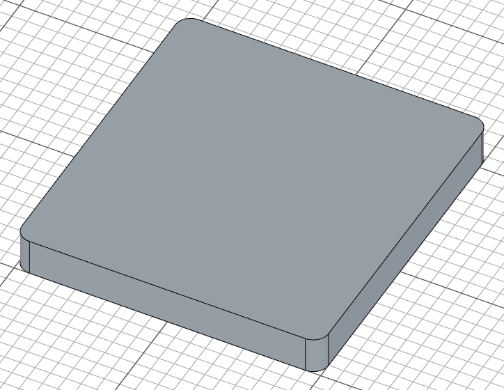
Sketch a rounded rectangle on the XY plane and extrude it to create the base plate. In a constraint sketch (the true argument to sketch()), each line is drawn with explicit start/end coordinates, and constraints pin the shape: coincident joins the corners, horizontal/vertical square up the sides, fix anchors one corner, and two distance dimensions carry the exam parameters B and A.
sketch("xy", () => {
    const b = line([0, 0], [B, 0]);
    const r = line([B, 0], [B, A]);
    const t = line([B, A], [0, A]);
    const l = line([0, A], [0, 0]);
    coincident(b.end(), r.start());
    coincident(r.end(), t.start());
    coincident(t.end(), l.start());
    coincident(l.end(), b.start());
    horizontal(b);
    vertical(r);
    horizontal(t);
    vertical(l);
    fix(b.start(), [0, 0]);
    distance(b.start(), b.end(), B);
    distance(r.start(), r.end(), A);
    fillet(10, b, r, t, l);
})

const base = extrude(25);
The four lines form a B x A (200 x 213) rectangle. Because the dimensions are the distance constraints, changing A or B re-solves the sketch and the whole part updates — exactly what the exam requires. fillet(10, b, r, t, l) rounds all four shared corners with a 10mm radius, and the base is extruded 25mm thick.
Step 2: L-Shaped Support
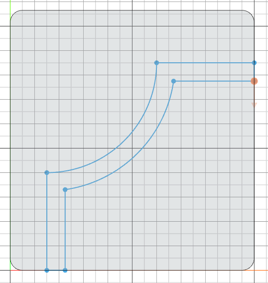
The L-shaped support sits on top of the base. Its profile is made of two perpendicular lines connected by an arc, then offset and closed into a wall of constant thickness.
Sketch the profile
sketch("xy", () => {
    const l1 = line([leftOffset, 0], [leftOffset, 80]);
    const a = arc([leftOffset, 80], [B - 80, C], [leftOffset, C]);
    const l2 = line([B, C], [B - 80, C]);
    coincident(l1.end(), a.start());
    coincident(l2.end(), a.end());
    vertical(l1);
    horizontal(l2);
    fix(l1.start(), [leftOffset, 0]);
    fix(l2.start(), [B, C]);
    radius(a, C - 80);
    offset(15, l1, a, l2).close();
});
l1is the 80mm vertical leg starting at the support's left edge;l2is the 80mm horizontal leg ending at[B - 80, C]arc(start, end, center)takes the arc's start, end, and center — here it spans between the two leg endpoints around[leftOffset, C], forming the curved corner of the L. The coordinates are exact, and thecoincident,radius, andfixconstraints record the intent: the arc's ends meet the legs, and its radius isC - 80offset(15, l1, a, l2)offsets the whole chain by 15mm to give the support wall thickness, and.close()caps the two open ends with straight lines, closing the profile
Extrude the support
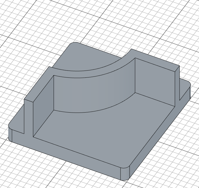
const support = extrude(95)
The support is extruded 95mm upward from the base plane. Since it shares the same XY sketch plane as the base, it rises from ground level and extends well above the 25mm base plate.
Step 3: Cylindrical Pipes
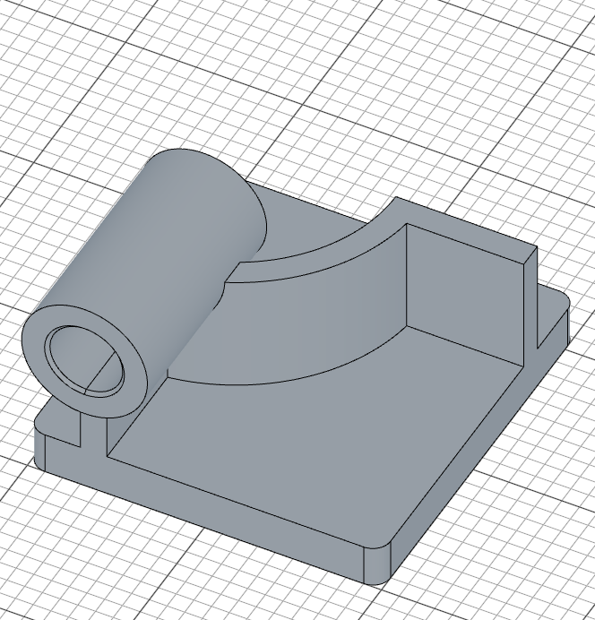
Two hollow pipes extend from the support — one from the front face and one from the right face. Each is created by extruding a circle on an offset reference plane, then cutting a smaller bore through it.
Pipe 1 — Sketch on offset plane
First, create a reference plane offset 10mm from the front of the support. Then sketch a circle for the pipe's outer profile:
const p1 = plane("front", 10);

sketch(p1, () => {
    const c = circle([leftOffset + 7.5, 95], X);
    fix(c.center(), [leftOffset + 7.5, 95]);
    diameter(c, X);
});
plane("front", 10)creates a reference plane 10mm in front of the support facecircle(center, d)places the outer circle at[leftOffset + 7.5, 95]— the support's left edge shifted 7.5mm to sit centered on the support wall, 95mm upfixlocks the center at that position anddiameter(c, X)dimensions it with the exam parameterX(= A/3), leaving the circle fully constrained

Pipe 1 — Extrude, bore, and chamfer
const cylBody1 = extrude(-D)
sketch(cylBody1.startFaces(), () => {
    const rim = project(cylBody1.startFaces()).guide();
    const bore = circle([0, 0], E);
    concentric(bore, rim);
    diameter(bore, E);
})
const cylCut1 = cut()

chamfer(2, cylCut1.startEdges(), cylCut1.endEdges())
extrude(-D)extends the pipe backward (away from the viewer) byD(130mm) — the negative direction pushes it into and through the support- The bore sketch sits on the pipe's far end face.
project(...)brings the face's circular rim into the sketch as a fixed reference (.guide()keeps it out of the profile), andconcentric(bore, rim)locks the bore onto the pipe's axis — no coordinates needed, so the bore follows the pipe wherever the parameters put it diameter(bore, E)dimensions the bore toE(41mm);cut()then bores through the entire pipe, making it hollowchamfer(2, ...)adds a 2mm chamfer to both the start and end edges of the bore
Pipe 2 — Right
The right pipe follows the same pattern on the right side of the support:
const p2 = plane("right", B + 10)

sketch(p2, () => {
    const c = circle([C - 7.5, 95], Y);
    fix(c.center(), [C - 7.5, 95]);
    diameter(c, Y);
});

const cylBody2 = extrude(-D)
sketch(cylBody2.startFaces(), () => {
    const rim = project(cylBody2.startFaces()).guide();
    const bore = circle([0, 0], E);
    concentric(bore, rim);
    diameter(bore, E);
})
const cylCut2 = cut()

chamfer(2, cylCut2.startEdges(), cylCut2.endEdges())
plane("right", B + 10)creates a reference plane 10mm beyond the right edge of the base- The circle at
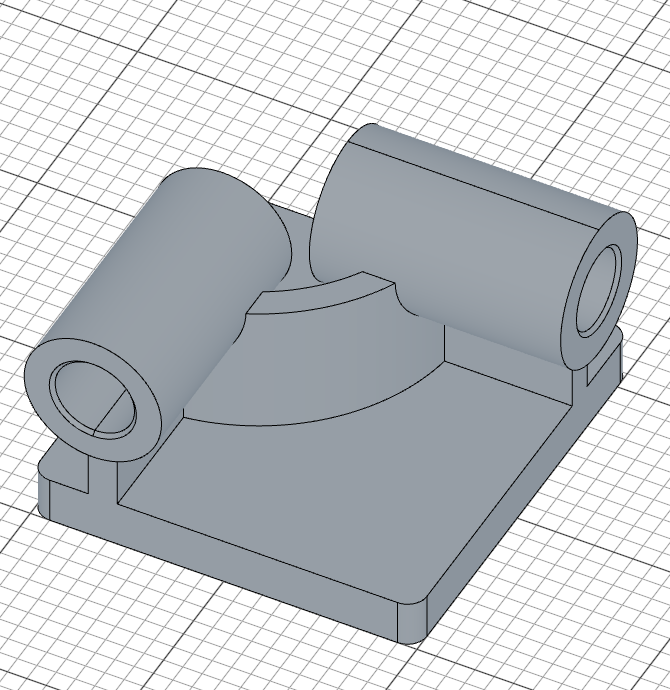
[C - 7.5, 95]centers the pipe on the support wall on the right side - The extrude, projected-rim bore, cut, and chamfer steps are identical to Pipe 1, but with diameter
Y(= B/3 + 10) for the outer circle
Step 4: Corner Block & Counterbore
A rectangular block is added at the front-right corner of the base, with a through-all hole and a counterbore on top.
Corner sketch
sketch("xy", () => {
    const cb = line([B, 0], [B - 60, 0]);
    const cr = line([B - 60, 0], [B - 60, 60]);
    const ct = line([B - 60, 60], [B, 60]);
    const cl = line([B, 60], [B, 0]);
    coincident(cb.end(), cr.start());
    coincident(cr.end(), ct.start());
    coincident(ct.end(), cl.start());
    coincident(cl.end(), cb.start());
    horizontal(cb);
    vertical(cr);
    horizontal(ct);
    vertical(cl);
    fix(cb.start(), [B, 0]);
    distance(cb.start(), cb.end(), 60);
    distance(cr.start(), cr.end(), 60);
    fillet(10, cl, cb);
    fillet(15, cr, ct);
});
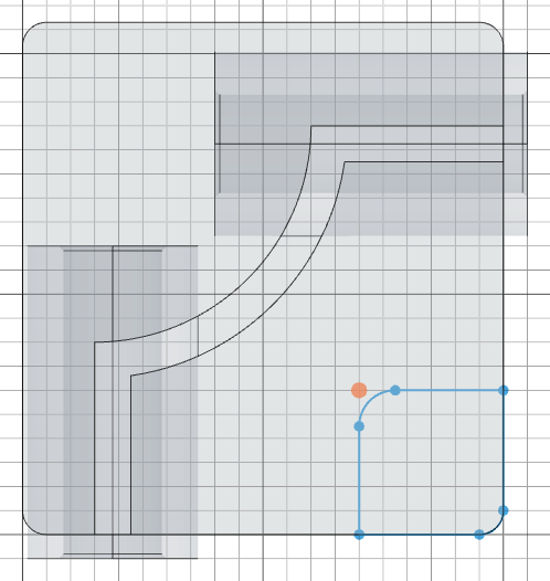
The four lines trace a 60x60 square whose anchored corner sits at [B, 0] — the right edge of the base — extending left and upward. Only two corners are rounded: fillet(10, cl, cb) rounds the corner the two named lines share (at [B, 0]) with a 10mm radius, and fillet(15, cr, ct) rounds the opposite corner (at [B - 60, 60]) with 15mm. The other two corners stay sharp.
Corner extrusion
const corner = extrude(35);
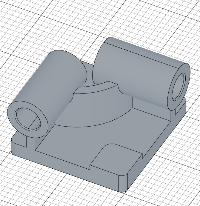
The block is extruded 35mm, taller than the 25mm base plate.
Through-all hole and counterbore
sketch(plane("xy", 35), () => {
    const c = circle([B - 30, 30], 15);
    fix(c.center(), [B - 30, 30]);
    diameter(c, 15);
})
cut()

sketch(plane("xy", 35), () => {
    const c = circle([B - 30, 30], 30);
    fix(c.center(), [B - 30, 30]);
    diameter(c, 30);
})
cut(10)
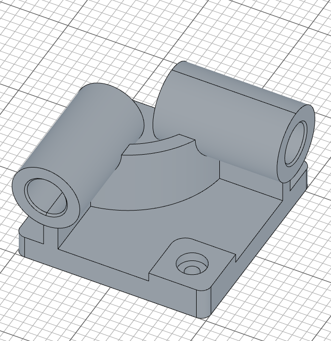
- Both circles sit on a plane at the block's top (
plane("xy", 35)— the block is 35mm tall), centered on the block at[B - 30, 30] - The first sketch is a 15mm diameter circle, and
cut()with no depth argument cuts through the entire block - The second is a larger 30mm diameter circle on the same plane, and
cut(10)cuts only 10mm deep — creating the counterbore recess
Step 5: Face Pocket
The final feature of Part 1 is a pocket cut into the top of the base plate. It's created by projecting the L-shaped support's footprint, offsetting it inward, and cutting down.
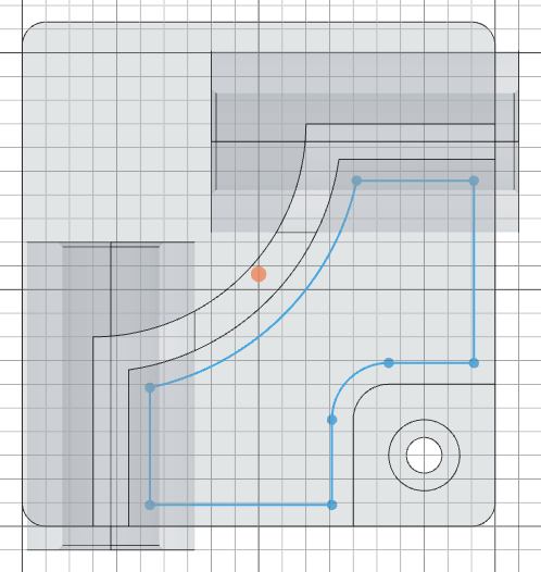
Select and project the face
const topFace = select(face().onPlane("xy", 25).hasEdge(edge().line(45)));

sketch(base.endFaces(), () => {
    const p = project(topFace).guide();
    offset(-9, p);
});
face().onPlane("xy", 25)finds faces at the top of the base plate (25mm height).hasEdge(edge().line(45))narrows it to the face that has a 45mm long line edge — this is the L-shaped support's footprintproject(topFace)projects the outline of that face into the sketch as fixed reference geometry;.guide()marks it as construction geometry so it doesn't become part of the profileoffset(-9, p)shrinks the projected outline inward by 9mm — the offset outline is the only profile geometry, so it alone defines the pocket
Cut the pocket
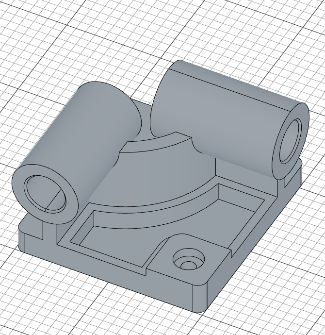
const c = cut(20)
cut(20) removes material 20mm deep, creating the pocket.
Fillet the pocket edges
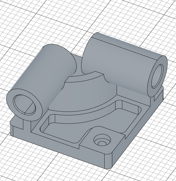
fillet(10, c.internalEdges())
c.internalEdges() selects the internal edges of the pocket (the edges at the bottom where the cut meets the base), and fillet(10, ...) rounds them with a 10mm fillet.
Part 1 — Full Code
Open this model in the 3D viewer// @screenshot waitForInput
import { arc, chamfer, circle, cut, extrude, fillet, line, offset, plane, project, select, sketch } from 'fluidcad/core';
import { coincident, concentric, diameter, distance, fix, horizontal, radius, tangent, vertical } from 'fluidcad/constraints';
import { edge, face } from 'fluidcad/filters';
// CSWP Exam Parameters — Stage 1
const A = 213;
const B = 200;
const C = 170;
const D = 130;
const E = 41;
const X = A / 3;
const Y = B / 3 + 10;
const leftOffset = B - C;
// Base plate
sketch("xy", () => {
const b = line([0, 0], [B, 0]);
const r = line([B, 0], [B, A]);
const t = line([B, A], [0, A]);
const l = line([0, A], [0, 0]);
coincident(b.end(), r.start());
coincident(r.end(), t.start());
coincident(t.end(), l.start());
coincident(l.end(), b.start());
horizontal(b);
vertical(r);
horizontal(t);
vertical(l);
fix(b.start(), [0, 0]);
distance(b.start(), b.end(), B);
distance(r.start(), r.end(), A);
fillet(10, b, r, t, l);
})
const base = extrude(25);
// L-shaped support
sketch("xy", () => {
const l1 = line([leftOffset, 0], [leftOffset, 80]);
const a = arc([leftOffset, 80], [B - 80, C], [leftOffset, C]);
const l2 = line([B, C], [B - 80, C]);
coincident(l1.end(), a.start());
coincident(l2.end(), a.end());
vertical(l1);
horizontal(l2);
fix(l1.start(), [leftOffset, 0]);
fix(l2.start(), [B, C]);
radius(a, C - 80);
offset(15, l1, a, l2).close();
});
const support = extrude(95)
// Pipe 1 — front
const p1 = plane("front", 10);
sketch(p1, () => {
const c = circle([leftOffset + 7.5, 95], X);
fix(c.center(), [leftOffset + 7.5, 95]);
diameter(c, X);
});
const cylBody1 = extrude(-D)
sketch(cylBody1.startFaces(), () => {
const rim = project(cylBody1.startFaces()).guide();
const bore = circle([0, 0], E);
concentric(bore, rim);
diameter(bore, E);
})
const cylCut1 = cut()
chamfer(2, cylCut1.startEdges(), cylCut1.endEdges())
// Pipe 2 — right
const p2 = plane("right", B + 10)
sketch(p2, () => {
const c = circle([C - 7.5, 95], Y);
fix(c.center(), [C - 7.5, 95]);
diameter(c, Y);
});
const cylBody2 = extrude(-D)
sketch(cylBody2.startFaces(), () => {
const rim = project(cylBody2.startFaces()).guide();
const bore = circle([0, 0], E);
concentric(bore, rim);
diameter(bore, E);
})
const cylCut2 = cut()
chamfer(2, cylCut2.startEdges(), cylCut2.endEdges())
// Corner block
sketch("xy", () => {
const cb = line([B, 0], [B - 60, 0]);
const cr = line([B - 60, 0], [B - 60, 60]);
const ct = line([B - 60, 60], [B, 60]);
const cl = line([B, 60], [B, 0]);
coincident(cb.end(), cr.start());
coincident(cr.end(), ct.start());
coincident(ct.end(), cl.start());
coincident(cl.end(), cb.start());
horizontal(cb);
vertical(cr);
horizontal(ct);
vertical(cl);
fix(cb.start(), [B, 0]);
distance(cb.start(), cb.end(), 60);
distance(cr.start(), cr.end(), 60);
fillet(10, cl, cb);
fillet(15, cr, ct);
});
const corner = extrude(35);
// Through-all hole — on a plane at the block's top (z = 35), centered on the block
sketch(plane("xy", 35), () => {
const c = circle([B - 30, 30], 15);
fix(c.center(), [B - 30, 30]);
diameter(c, 15);
})
cut()
// Counterbore
sketch(plane("xy", 35), () => {
const c = circle([B - 30, 30], 30);
fix(c.center(), [B - 30, 30]);
diameter(c, 30);
})
cut(10)
// Face pocket
const topFace = select(face().onPlane("xy", 25).hasEdge(edge().line(45)));
sketch(base.endFaces(), () => {
const p = project(topFace).guide();
offset(-9, p);
});
const c = cut(20)
fillet(10, c.internalEdges())
Verify with exam answers
With the Stage 1 test 1 parameters above (A=213, B=200, C=170, D=130, E=41), the mass should be 14207.34 grams (using Alloy Steel with density 0.0077 g/mm^3). Try changing the parameters to test 2 (A=225, B=210, C=176, D=137, E=39) and test 3 (A=209, B=218, C=169, D=125, E=41) to verify you get 16490.45 g and 15100.47 g respectively.
Part 2: Modify the Part
Stage 2 of the CSWP exam modifies the initial part. The key changes are:
- Remove corner radii from the base plate
- Change Y formula from
B/3 + 10toB/3 + 15 - Change chamfers to angled (2mm x 30 degrees)
- Remove the corner block (no counterbore hole)
- Add a second pocket cut into the base
- Add a key slot on the front pipe
- Add fillets on the base plate side edges
Update the parameters at the top of your file:
// CSWP Exam Parameters — Stage 2
const A = 221;
const B = 211;
const C = 165;
const D = 121;
const E = 37;
const X = A / 3;
const Y = B / 3 + 15;   // changed from B/3 + 10

const leftOffset = B - C;
Step 6: Angled Chamfers & Second Pocket
Base plate and chamfer changes
The base plate no longer has rounded corners — the sketch is the same four constrained lines, minus the fillet(10, ...) statement:
sketch("xy", () => {
    const b = line([0, 0], [B, 0]);
    const r = line([B, 0], [B, A]);
    const t = line([B, A], [0, A]);
    const l = line([0, A], [0, 0]);
    coincident(b.end(), r.start());
    coincident(r.end(), t.start());
    coincident(t.end(), l.start());
    coincident(l.end(), b.start());
    horizontal(b);
    vertical(r);
    horizontal(t);
    vertical(l);
    fix(b.start(), [0, 0]);
    distance(b.start(), b.end(), B);
    distance(r.start(), r.end(), A);
})
The pipe chamfers change from equal-distance to angled. Instead of chamfer(2, ...), use:
chamfer(2, 30, true, cylCut1.startEdges(), cylCut1.endEdges())
The three arguments (2, 30, true) specify a 2mm distance at a 30-degree angle, with true indicating the angle is measured from the face rather than the edge.
First pocket — different face selection
Since the corner block is removed, the face selector changes. Instead of matching a face with a 45-degree edge, use edge count:
const topFace1 = select(face().onPlane("xy", 25).edgeCount(5));

sketch(base.endFaces(), () => {
    const p = project(topFace1).guide();
    offset(-9, p);
});

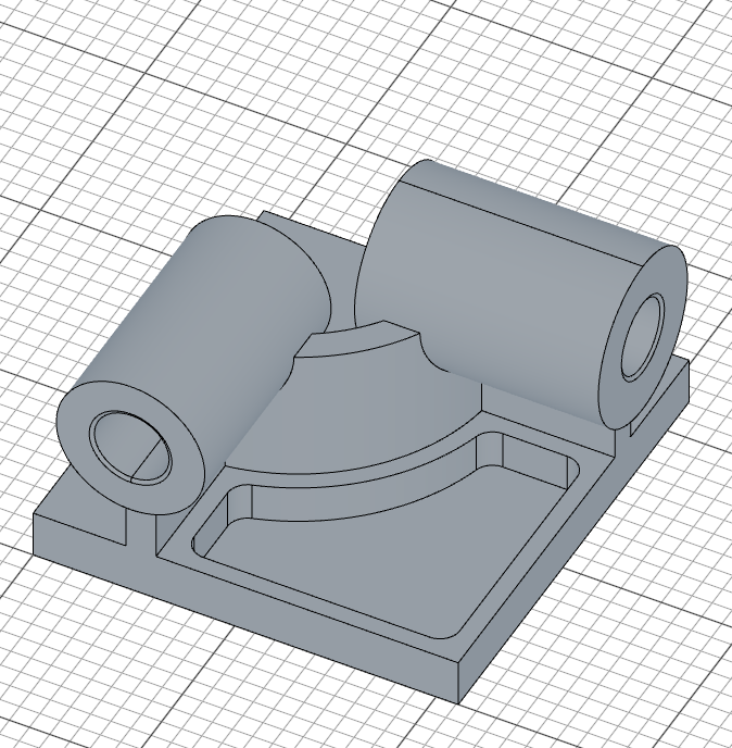
let c1 = cut(20)

fillet(10, c1.internalEdges())
edgeCount(5) selects the face with exactly 5 edges — the L-shaped footprint without the corner block interfering. The rest follows the same project-offset-cut-fillet pattern as Part 1.
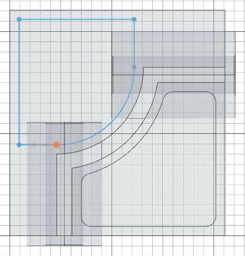
Second pocket — sketch
A second pocket is cut on the opposite side of the base, using a manually constructed profile that mirrors the L-shape:
sketch(base.endFaces(), () => {
    const outerOffset = 9;
    const l1 = line([outerOffset, A - outerOffset], [B - 80 - outerOffset, A - outerOffset]);
    const l2 = line([outerOffset, A - outerOffset], [outerOffset, 80 + outerOffset]);
    const l3 = line([outerOffset, 80 + outerOffset], [leftOffset, 80 + outerOffset]);
    const l4 = line([B - 80 - outerOffset, A - outerOffset], [B - 80 - outerOffset, C]);
    const a = arc([B - 80 - outerOffset, C], [leftOffset, 80 + outerOffset], [leftOffset, C]).cw();
    coincident(l1.start(), l2.start());
    coincident(l2.end(), l3.start());
    coincident(l1.end(), l4.start());
    coincident(l4.end(), a.start());
    coincident(l3.end(), a.end());
    horizontal(l1);
    vertical(l2);
    horizontal(l3);
    vertical(l4);
    tangent(l4, a);
    fix(l1.start(), [outerOffset, A - outerOffset]);
});
- The profile starts near the top-left corner of the base, offset 9mm inward from the edges
- Four lines trace the pocket boundary, following the L-shape in reverse;
coincidentjoins each junction andhorizontal/verticalkeep the sides square - The arc closes the two open endpoints around center
[leftOffset, C]— the same center as the support's arc..cw()picks the clockwise sweep froml4down tol3, andtangent(l4, a)records that the arc leavesl4smoothly (it meetsl3smoothly too, for the same reason), mirroring the support's curved corner
Second pocket — cut and fillet
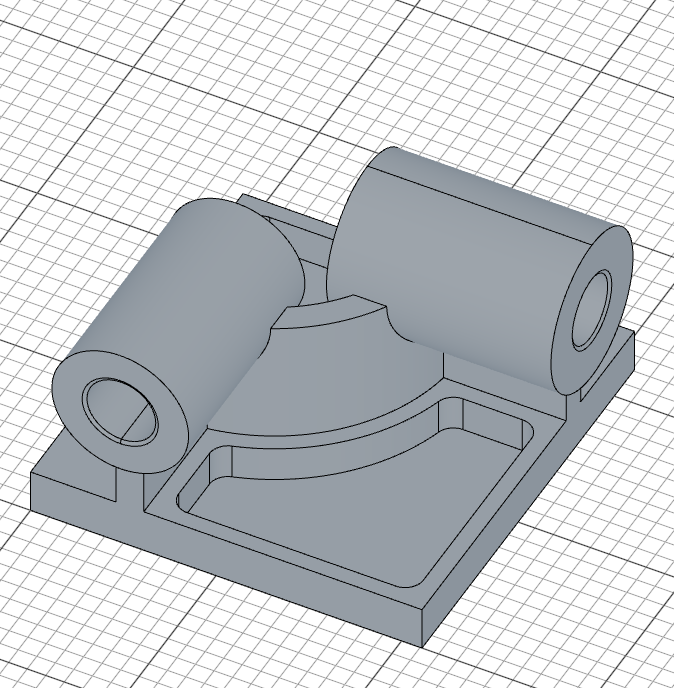
const c2 = cut(20)

fillet(10, c2.internalEdges())
The pocket is cut 20mm deep and its internal edges are filleted with a 10mm radius, matching the first pocket.
Step 7: Key Slot & Base Fillets
Key slot on front pipe
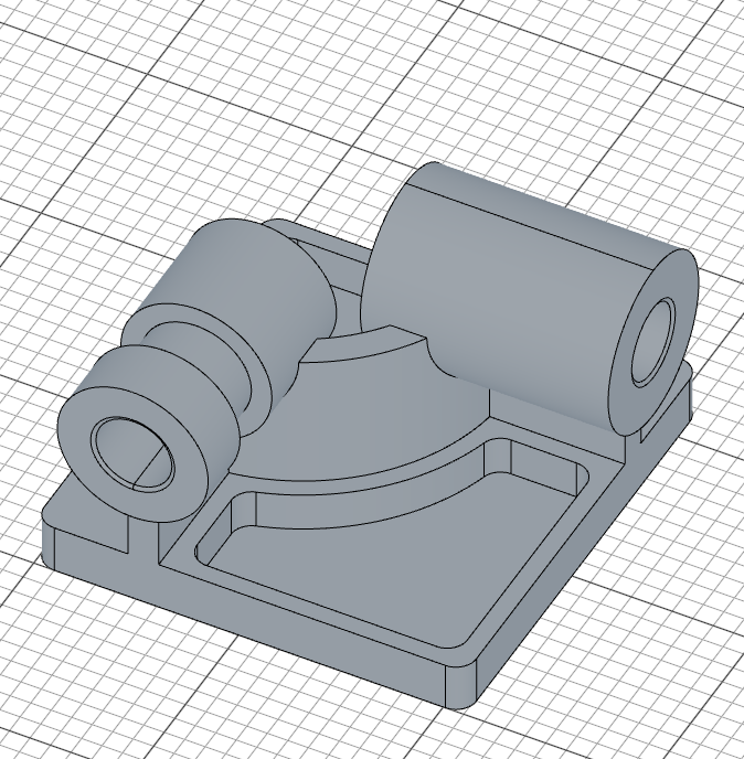
A key slot is cut into the front pipe. The profile is a ring with a rectangular keyway notch, drawn directly as one boundary: an outer arc that stops either side of the notch, three lines forming the notch, and a full inner circle. Everything is positioned relative to the pipe itself, via a projected reference:
sketch(plane(cylBody1.startFaces(), -30), () => {
    const rOut = X / 2;
    const key = 15;
    const xNotch = Math.sqrt(rOut * rOut - (key / 2) * (key / 2));
    const rim = project(cylBody1.startFaces()).guide();
    const a = arc([xNotch, key / 2], [xNotch, -key / 2], [0, 0]);
    const kTop = line([xNotch, key / 2], [rOut - key / 2, key / 2]);
    const kBack = line([rOut - key / 2, key / 2], [rOut - key / 2, -key / 2]);
    const kBottom = line([rOut - key / 2, -key / 2], [xNotch, -key / 2]);
    const inner = circle([0, 0], X - 20);
    coincident(a.start(), kTop.start());
    coincident(kTop.end(), kBack.start());
    coincident(kBack.end(), kBottom.start());
    coincident(kBottom.end(), a.end());
    horizontal(kTop);
    vertical(kBack);
    horizontal(kBottom);
    concentric(a, rim);
    radius(a, rOut);
    concentric(inner, rim);
    diameter(inner, X - 20);
    distance(rim.center(), kTop, key / 2);
    distance(rim.center(), kBottom, key / 2);
    distance(rim.center(), kBack, rOut - key / 2);
});

cut(30);
plane(cylBody1.startFaces(), -30)creates a sketch plane 30mm behind the pipe's far endproject(cylBody1.startFaces())brings the pipe's circular rim in as a fixed reference; both the outer arc and the inner circle are madeconcentricwith it, so the slot stays centered on the pipe no matter what the parameters are- The outer arc has the pipe's radius (
radius(a, rOut)); the inner circle is the bore ring, 10mm smaller in radius (diameter(inner, X - 20)) - The three
distanceconstraints place the notch: 15mm wide (key / 2each side of the pipe axis) and reaching 7.5mm inside the outer rim. The guess coordinates put the notch on the pipe's +X side, which picks that solution cut(30)cuts this profile 30mm deep into the pipe, leaving the keyed ring groove
Base side fillets
fillet(10, base.sideEdges())
base.sideEdges() selects all vertical edges of the base plate, and fillet(10, ...) rounds them with a 10mm radius.
Part 2 — Full Code
Open this model in the 3D viewer// @screenshot waitForInput
import { arc, chamfer, circle, cut, extrude, fillet, line, offset, plane, project, select, sketch } from 'fluidcad/core';
import { coincident, concentric, diameter, distance, fix, horizontal, radius, tangent, vertical } from 'fluidcad/constraints';
import { edge, face } from 'fluidcad/filters';
// CSWP Exam Parameters — Stage 2
const A = 221;
const B = 211;
const C = 165;
const D = 121;
const E = 37;
const X = A / 3;
const Y = B / 3 + 15;
const leftOffset = B - C;
// Base plate (no corner radii in Stage 2)
sketch("xy", () => {
const b = line([0, 0], [B, 0]);
const r = line([B, 0], [B, A]);
const t = line([B, A], [0, A]);
const l = line([0, A], [0, 0]);
coincident(b.end(), r.start());
coincident(r.end(), t.start());
coincident(t.end(), l.start());
coincident(l.end(), b.start());
horizontal(b);
vertical(r);
horizontal(t);
vertical(l);
fix(b.start(), [0, 0]);
distance(b.start(), b.end(), B);
distance(r.start(), r.end(), A);
})
const base = extrude(25);
// L-shaped support
sketch("xy", () => {
const l1 = line([leftOffset, 0], [leftOffset, 80]);
const a = arc([leftOffset, 80], [B - 80, C], [leftOffset, C]);
const l2 = line([B, C], [B - 80, C]);
coincident(l1.end(), a.start());
coincident(l2.end(), a.end());
vertical(l1);
horizontal(l2);
fix(l1.start(), [leftOffset, 0]);
fix(l2.start(), [B, C]);
radius(a, C - 80);
offset(15, l1, a, l2).close();
});
const support = extrude(95)
// Pipe 1 — front (angled chamfer)
const p1 = plane("front", 10);
sketch(p1, () => {
const c = circle([leftOffset + 7.5, 95], X);
fix(c.center(), [leftOffset + 7.5, 95]);
diameter(c, X);
});
const cylBody1 = extrude(-D)
sketch(cylBody1.startFaces(), () => {
const rim = project(cylBody1.startFaces()).guide();
const bore = circle([0, 0], E);
concentric(bore, rim);
diameter(bore, E);
})
const cylCut1 = cut()
chamfer(2, 30, true, cylCut1.startEdges(), cylCut1.endEdges())
// Pipe 2 — right (angled chamfer)
const p2 = plane("right", B + 10)
sketch(p2, () => {
const c = circle([C - 7.5, 95], Y);
fix(c.center(), [C - 7.5, 95]);
diameter(c, Y);
});
const cylBody2 = extrude(-D)
sketch(cylBody2.startFaces(), () => {
const rim = project(cylBody2.startFaces()).guide();
const bore = circle([0, 0], E);
concentric(bore, rim);
diameter(bore, E);
})
const cylCut2 = cut()
chamfer(2, 30, true, cylCut2.startEdges(), cylCut2.endEdges())
// First pocket
const topFace1 = select(face().onPlane("xy", 25).edgeCount(5));
sketch(base.endFaces(), () => {
const p = project(topFace1).guide();
offset(-9, p);
});
let c1 = cut(20)
fillet(10, c1.internalEdges())
// Second pocket
sketch(base.endFaces(), () => {
const outerOffset = 9;
const l1 = line([outerOffset, A - outerOffset], [B - 80 - outerOffset, A - outerOffset]);
const l2 = line([outerOffset, A - outerOffset], [outerOffset, 80 + outerOffset]);
const l3 = line([outerOffset, 80 + outerOffset], [leftOffset, 80 + outerOffset]);
const l4 = line([B - 80 - outerOffset, A - outerOffset], [B - 80 - outerOffset, C]);
const a = arc([B - 80 - outerOffset, C], [leftOffset, 80 + outerOffset], [leftOffset, C]).cw();
coincident(l1.start(), l2.start());
coincident(l2.end(), l3.start());
coincident(l1.end(), l4.start());
coincident(l4.end(), a.start());
coincident(l3.end(), a.end());
horizontal(l1);
vertical(l2);
horizontal(l3);
vertical(l4);
tangent(l4, a);
fix(l1.start(), [outerOffset, A - outerOffset]);
});
const c2 = cut(20)
fillet(10, c2.internalEdges())
// Key slot on pipe 1 — the bore ring with its keyway, drawn as one profile.
// The notch sits symmetric about the pipe's +X axis, 15 wide and reaching
// 7.5 inside the outer rim (the legacy version assembled this with 2D
// booleans, which no longer exist).
sketch(plane(cylBody1.startFaces(), -30), () => {
const rOut = X / 2;
const key = 15;
const xNotch = Math.sqrt(rOut * rOut - (key / 2) * (key / 2));
const rim = project(cylBody1.startFaces()).guide();
const a = arc([xNotch, key / 2], [xNotch, -key / 2], [0, 0]);
const kTop = line([xNotch, key / 2], [rOut - key / 2, key / 2]);
const kBack = line([rOut - key / 2, key / 2], [rOut - key / 2, -key / 2]);
const kBottom = line([rOut - key / 2, -key / 2], [xNotch, -key / 2]);
const inner = circle([0, 0], X - 20);
coincident(a.start(), kTop.start());
coincident(kTop.end(), kBack.start());
coincident(kBack.end(), kBottom.start());
coincident(kBottom.end(), a.end());
horizontal(kTop);
vertical(kBack);
horizontal(kBottom);
concentric(a, rim);
radius(a, rOut);
concentric(inner, rim);
diameter(inner, X - 20);
distance(rim.center(), kTop, key / 2);
distance(rim.center(), kBottom, key / 2);
distance(rim.center(), kBack, rOut - key / 2);
});
cut(30);
// Base side fillets
fillet(10, base.sideEdges())
Verify with exam answers
With the Stage 2 test 4 parameters above (A=221, B=211, C=165, D=121, E=37), the mass should be 13206.40 grams. Try changing to test 5 (A=229, B=217, C=163, D=119, E=34) to verify you get 14208.00 g.
What you practiced
- Constrained rectangles — four
line()statements squared up withcoincident,horizontal/vertical,fix, anddistancedimensions carrying the exam parameters arc(start, end, center)— arcs drawn with explicit geometry, pinned withcoincident,radius, andtangentconstraintsoffset()and.close()— offsetting sketch geometry to create wall thickness, with automatic end capsplane()— creating offset reference planes for sketching on non-standard surfaceschamfer()— adding equal-distance and angled chamfers to edgesfillet()in 2D and 3D — rounding sketch corners, internal pocket edges, and base side edgescut()with and without depth — through-all cuts vs. depth-limited counterboresselect()withface()filters — selecting specific faces usingonPlane(),hasEdge(), andedgeCount()project()references — projecting face outlines as fixed reference geometry, then constraining against them withconcentricanddistance, or offsetting them into pocket profiles- Solution branches — letting exact guess coordinates pick which of several constraint solutions (like the keyway's side) the solver lands on