Building a 3D Printable Desk Organizer
In this tutorial, you'll build a four-compartment octagonal desk organizer with a square inner pocket, based on the original design by TooTallToby. You build it entirely from the FluidCAD workspace: the toolbar, the sketch tools, the constraint bar and the feature dialogs. Every dialog writes a line of code into your file as you apply it, so the full code at the end is what the UI produced, not something you type.
It covers sketching a regular octagon with the Polygon tool, rounding its corners with the sketch Fillet tool, extruding, chamfering and shelling a body, drawing a dimensioned rectangle and offsetting it, making a rotated construction plane, building a rib and patterning it around an axis, and trimming with a thin revolve cut.
Before you start
Open a workspace and create a new part file: click + in the top bar and type desk-organizer.fluid.js. The new tab opens on an empty scene. The screenshots use the light theme; the sun/moon button at the top right switches it.
A few UI habits you will use throughout:
- Ctrl+click adds an entity to the current selection. A plain click replaces it.
- The constraint bar appears under the toolbar while you sketch. Its buttons are icons; hover one for its name. A button lights up only when the current selection makes sense for it.
- The DOF pill at the bottom of the viewport counts the degrees of freedom left in a sketch and turns into Fully constrained when you are done.
- Every feature dialog shows the statement it is about to write, just under the dialog. Apply (or Enter) writes it; Exit (or Escape) discards it.
Step 1: Octagonal base
Start a sketch on the XY plane
Click Sketch in the toolbar. The Sketch dialog asks for a face or a plane, and the three origin planes appear in the viewport.
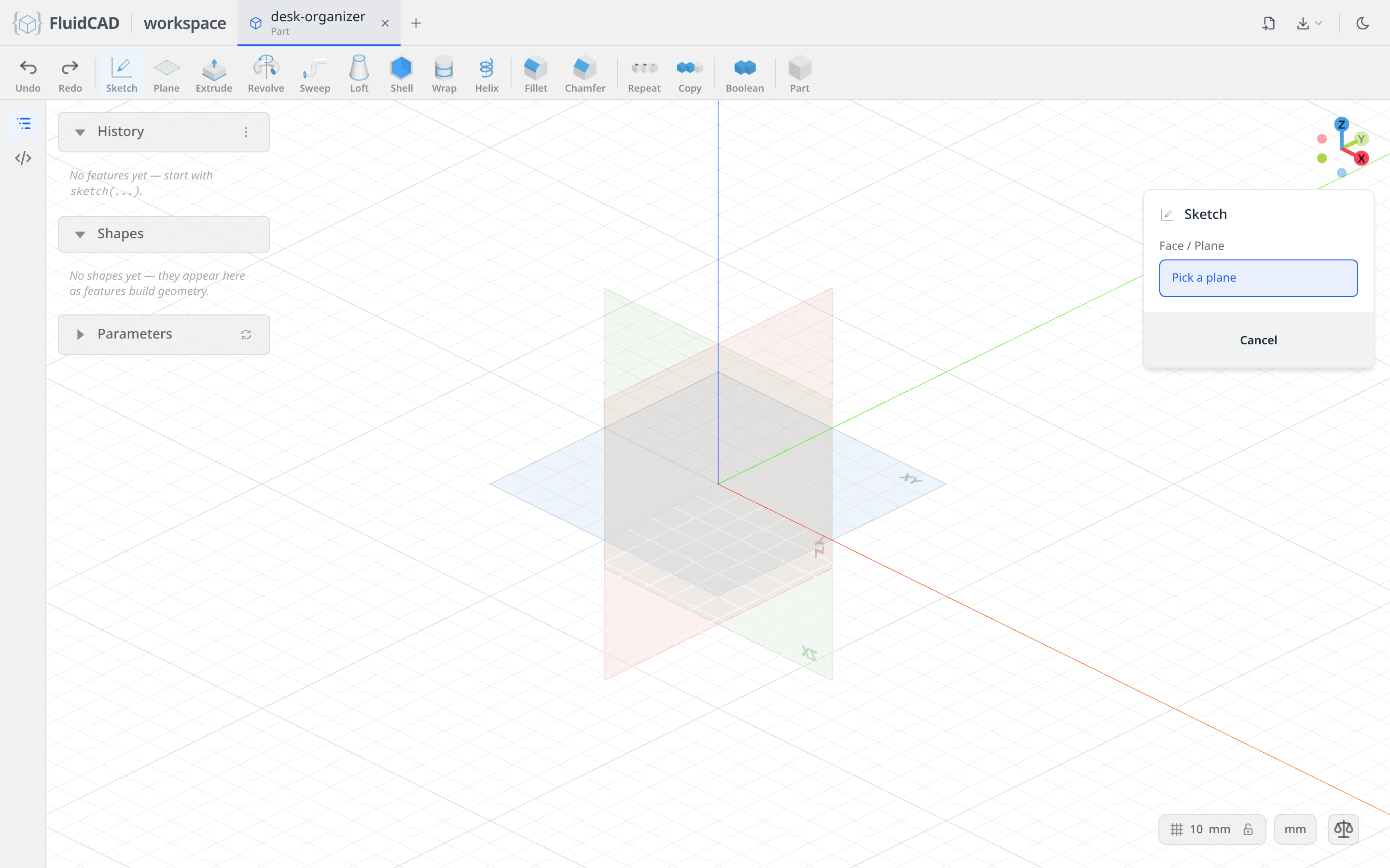
Click the XY plane. The camera locks onto it, the sketch toolbar replaces the feature toolbar, and the constraint bar appears above the viewport. The dialog now lists the sketch options: section view, camera lock, snapping, automatic constraint inference while drawing, and which constraint badges to display. Leave them all on.
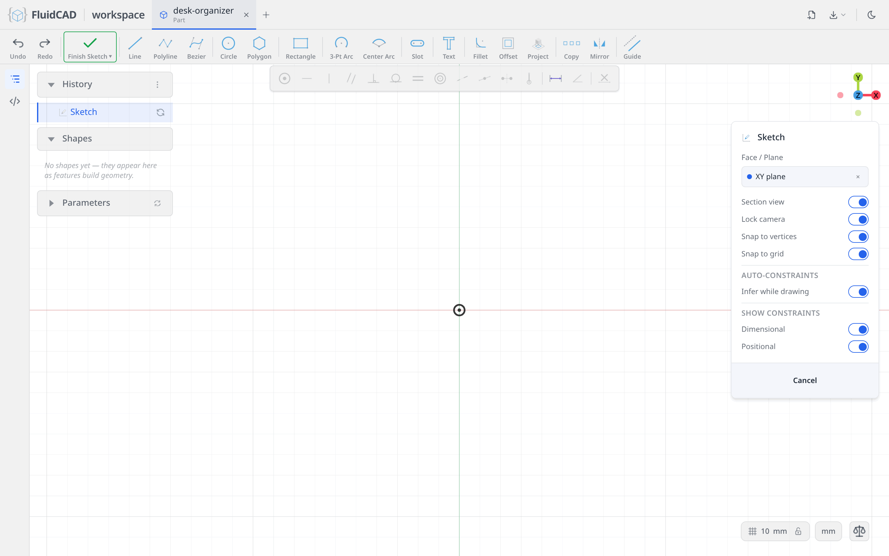
Draw the octagon with the Polygon tool
Pick the Polygon tool. Its button carries a small option menu for circumscribed or inscribed; leave it on circumscribed, so the size you type is measured across the flats rather than across the corners.
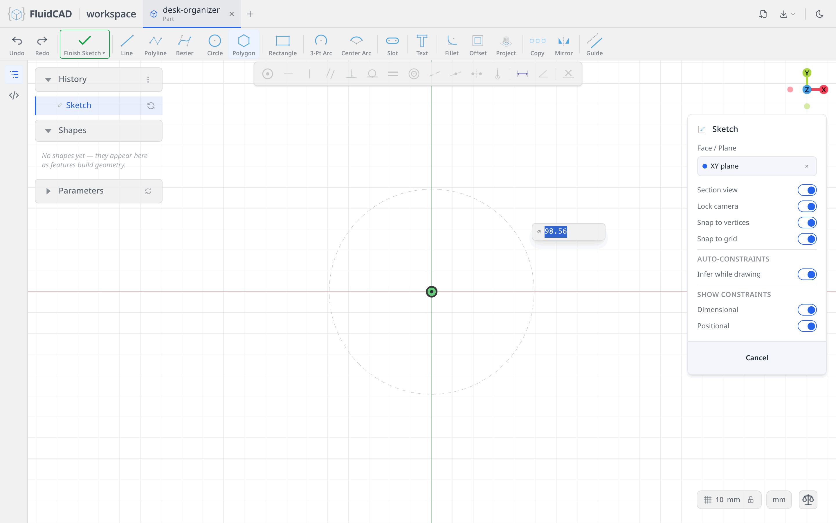
Click the origin for the center. A ⌀ readout follows the mouse; type 140 and press Enter.
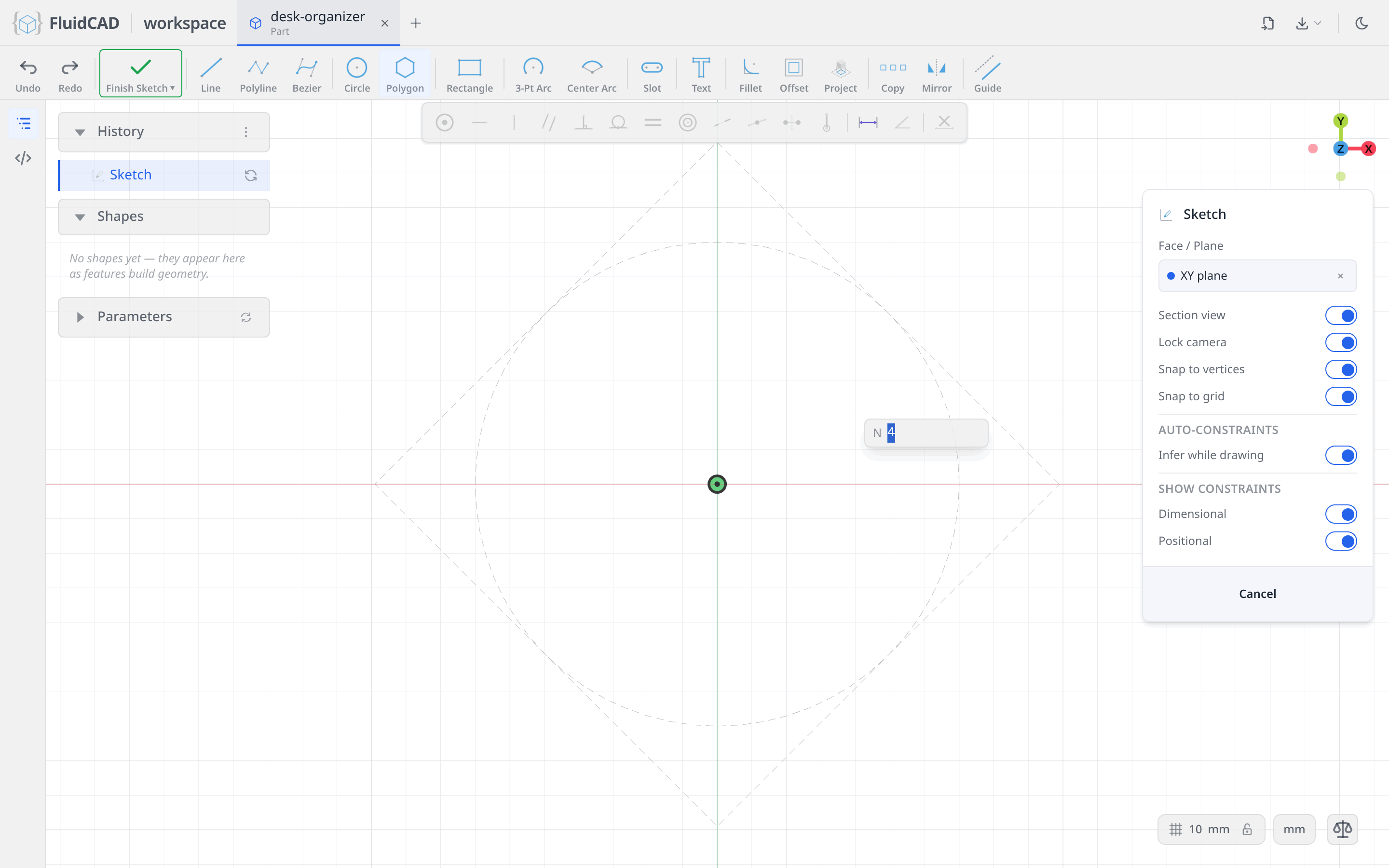
The readout switches to N, the number of sides. Moving the mouse previews the polygon; type 8 and press Enter.
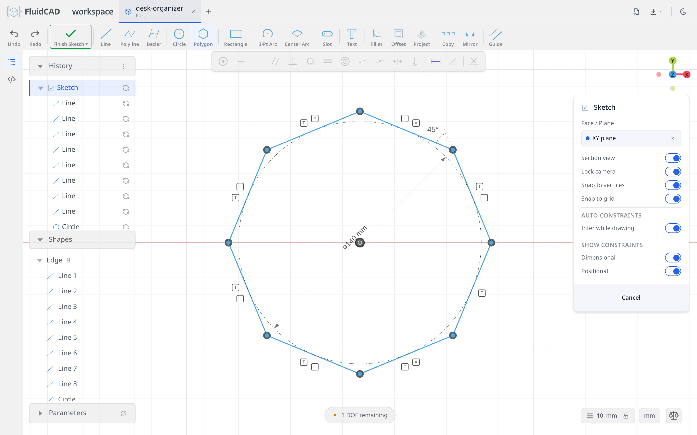
One tool, and the octagon arrives fully described: eight lines joined corner to corner, a dash-dot guide circle of diameter 140 centered on the origin, every side tangent to it, all sides equal, and a 45° angle between two neighbors. The badges around the profile are those constraints. The DOF pill reads 1 DOF remaining: the octagon can still spin about its center.
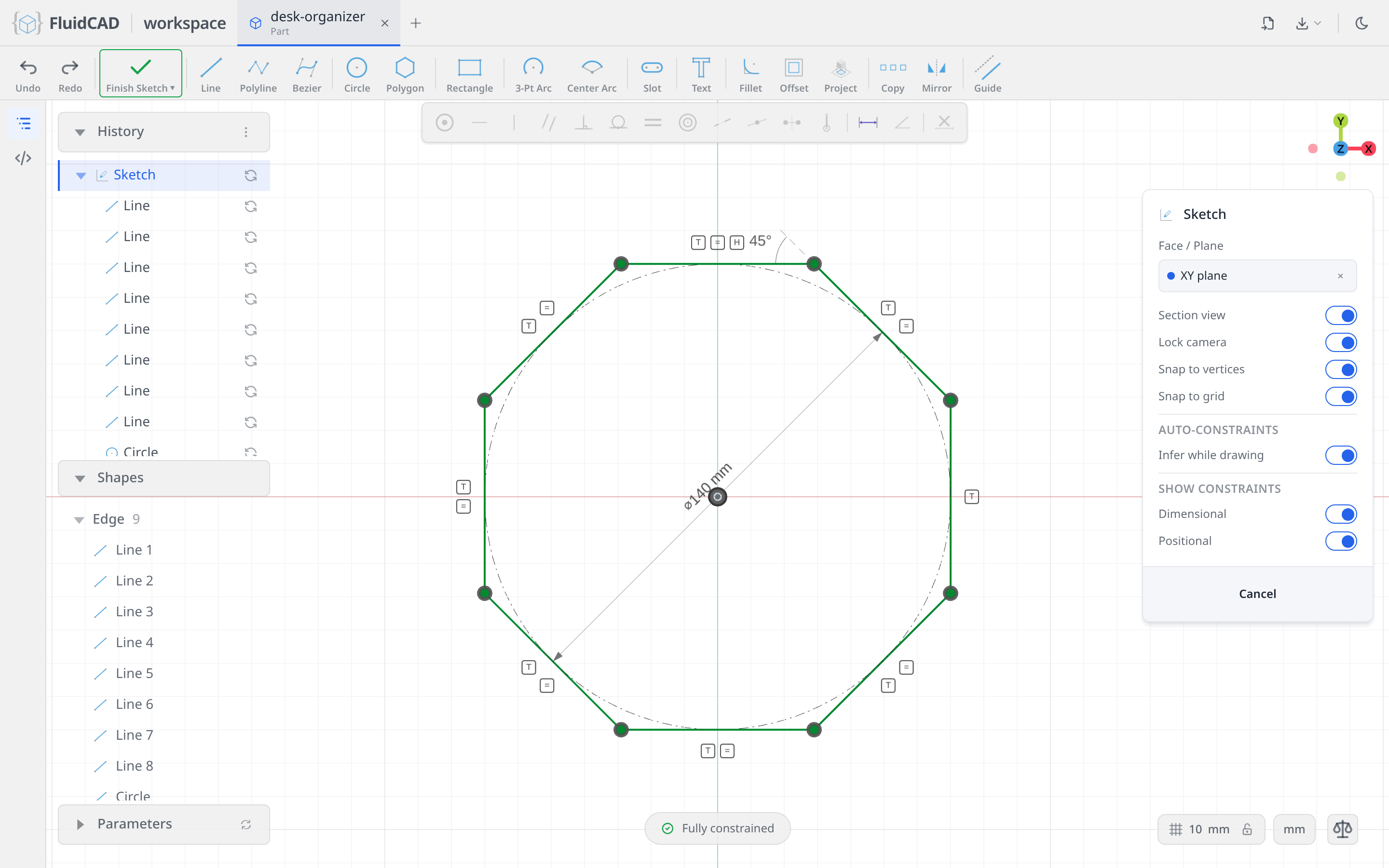
Click the top side, away from its midpoint where the guide circle touches it, and click Horizontal on the constraint bar. A flat now faces the X axis instead of a corner, and the pill reads Fully constrained. That orientation matters later: it lines up the inner square's diagonals with four of the flats.
Round the corners with the Fillet tool
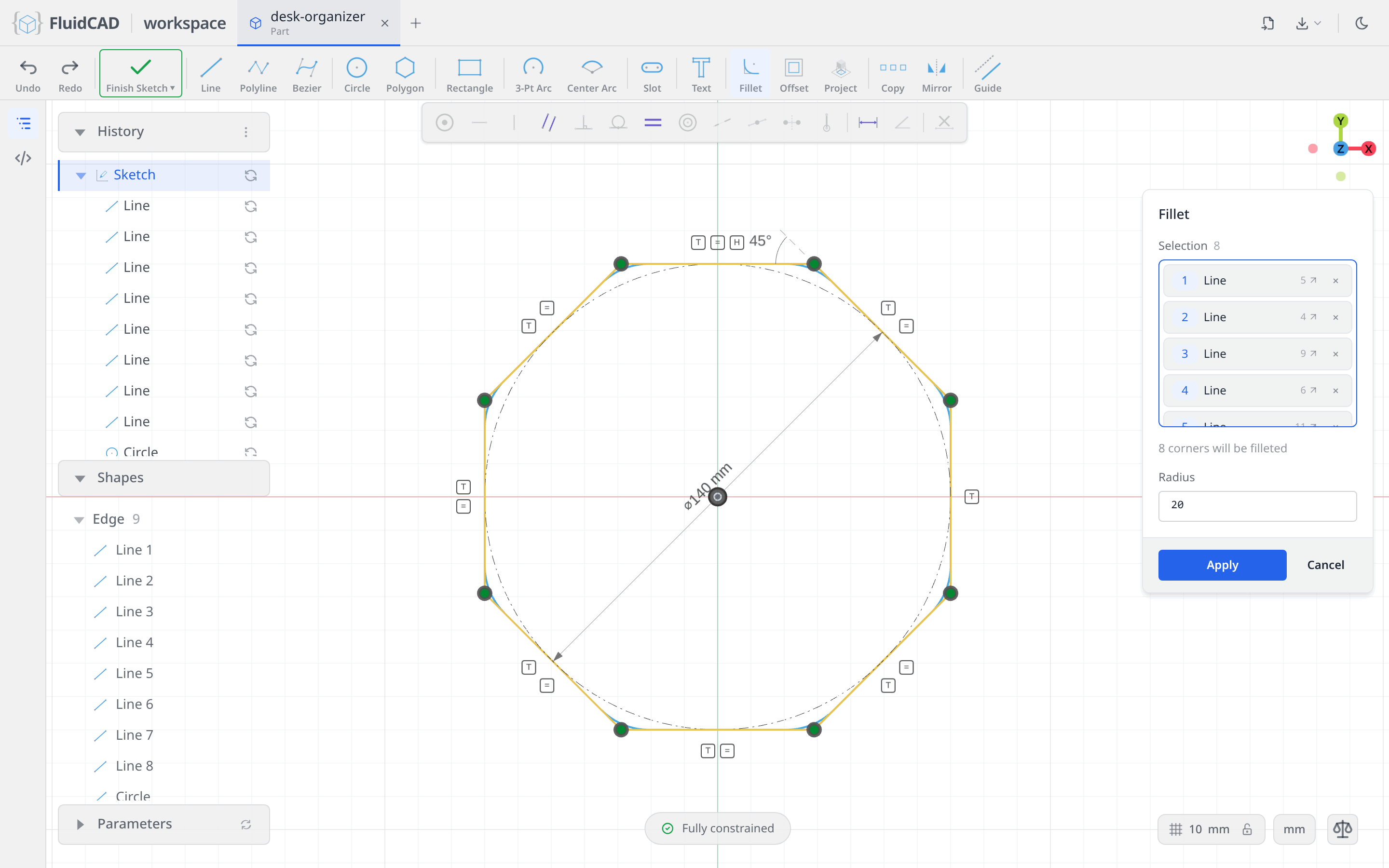
Pick Fillet in the sketch toolbar. Click each of the eight sides, near a corner so the pick does not land on the guide circle; the dialog counts them and reports 8 corners will be filleted. Set Radius to 20. The thin blue arcs at the corners are the preview.
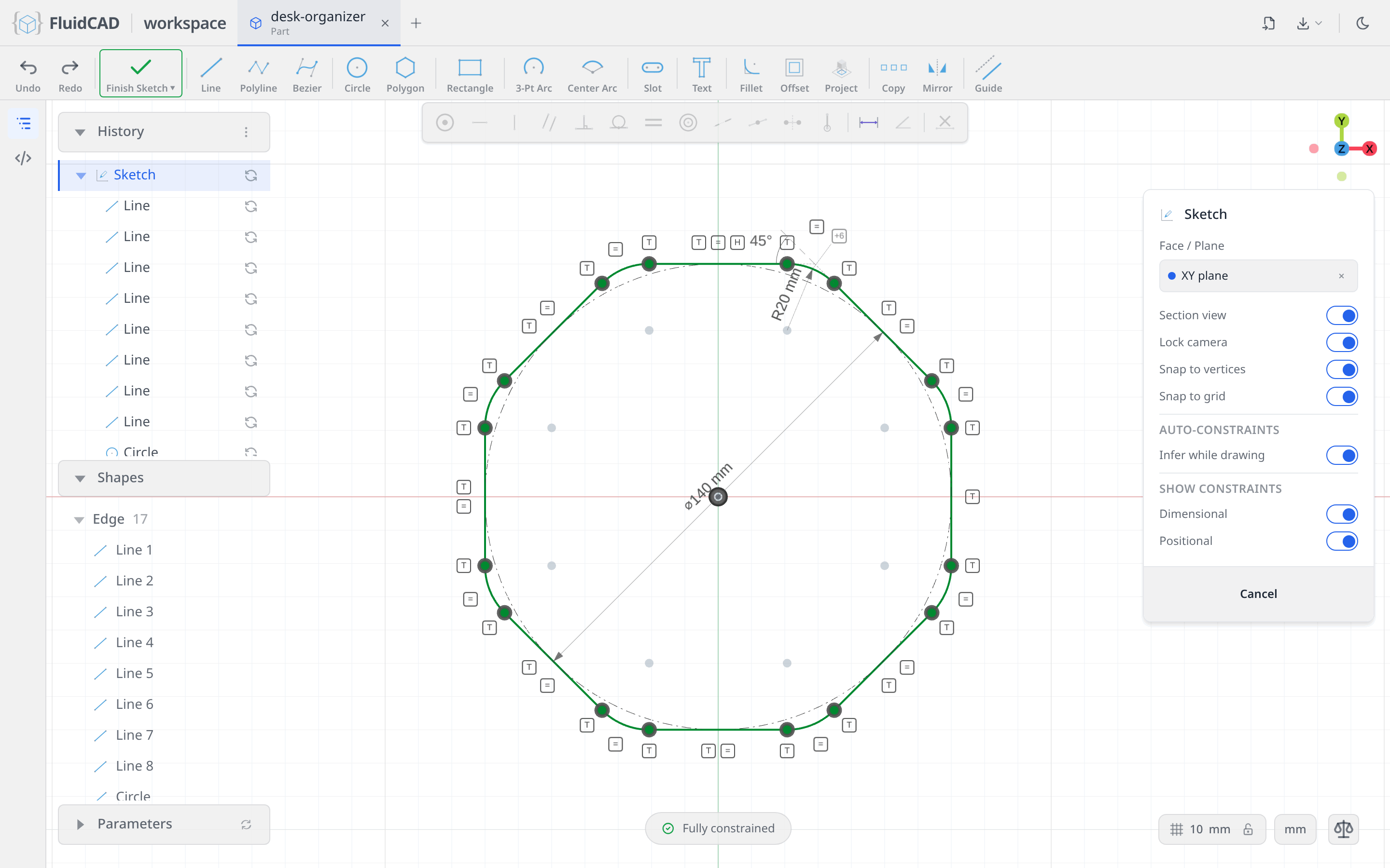
Click Apply. Each corner is replaced by an arc that is tangent to both of its sides, one arc carries the R20 dimension and the other seven are equal to it. The pill still reads Fully constrained.
Extrude the body
The 3D operations that take a sketch as input stay on the toolbar while the sketch is open. Click Extrude. The Extrude dialog opens with the sketch already in its Sketch slot. Set Distance to 110. The green ghost is a live preview of the solid the extrude will add, and the statement under the dialog reads extrude(110).
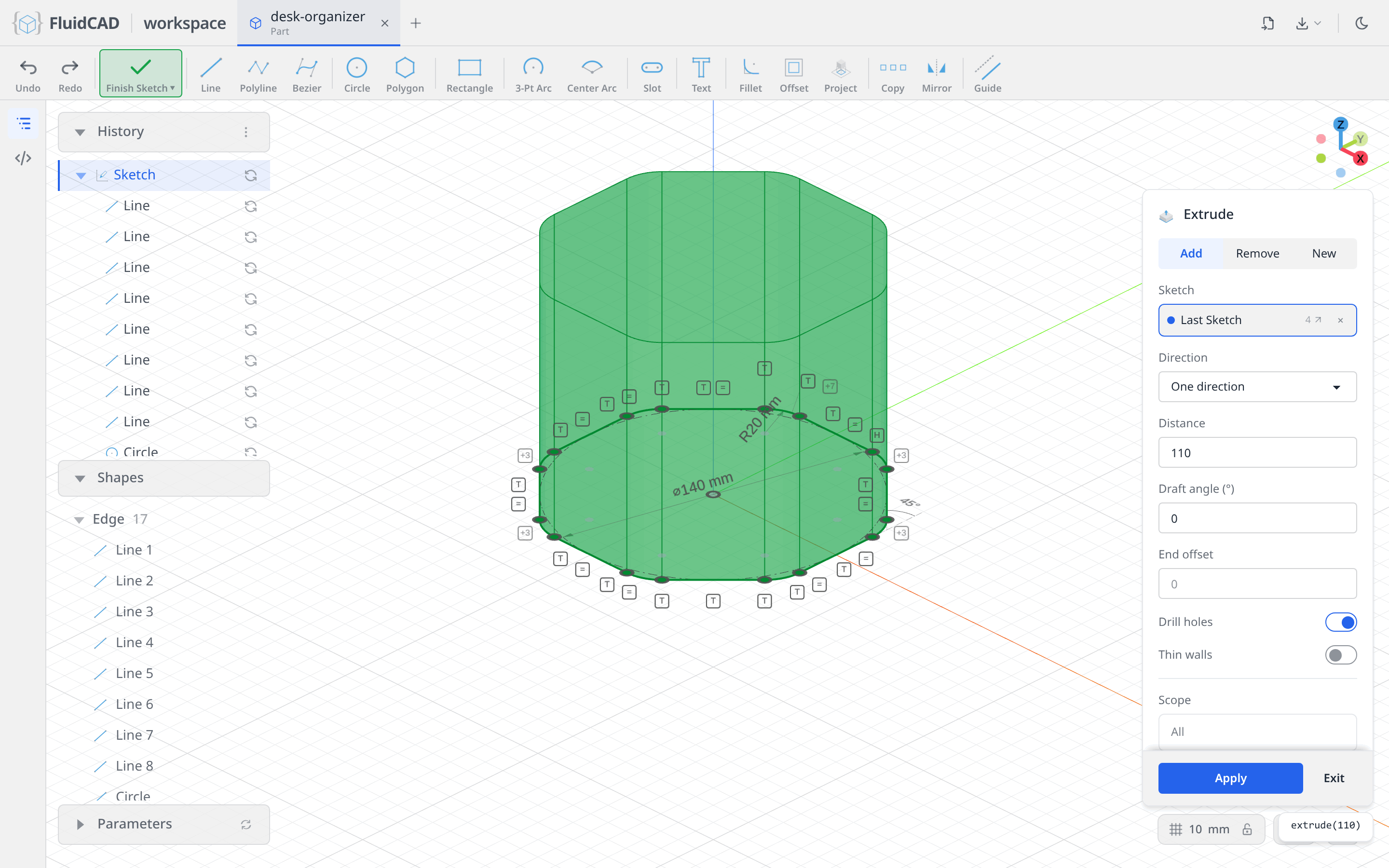
Click Apply. The prism appears, an Extrude row joins the History panel, and the Shapes panel lists the new solid.
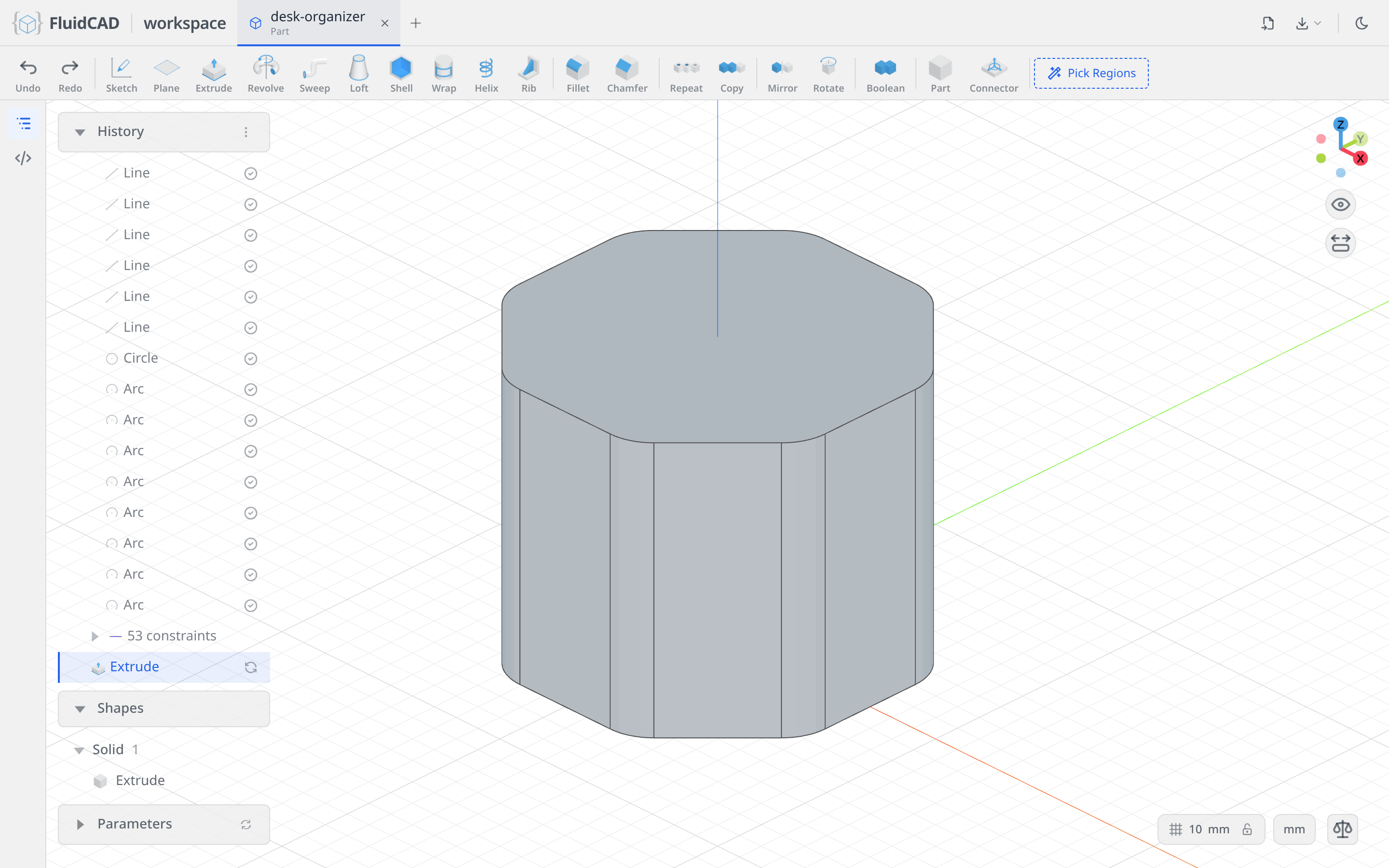
Step 2: Chamfer the bottom and shell from the top
Chamfer the bottom edges
Click Chamfer in the toolbar. The dialog asks you to pick edges. Click one edge of the bottom rim, then double-click it: a double-click expands the pick to the whole classified group the edge belongs to, here all sixteen edges of the bottom rim. Set Distance to 8.
The red band is the chamfer preview. The statement reads chamfer(8, e.startEdges()): FluidCAD recognised the rim as the start edges of the extrude and wrote the selection that way, so it survives edits to the sketch.
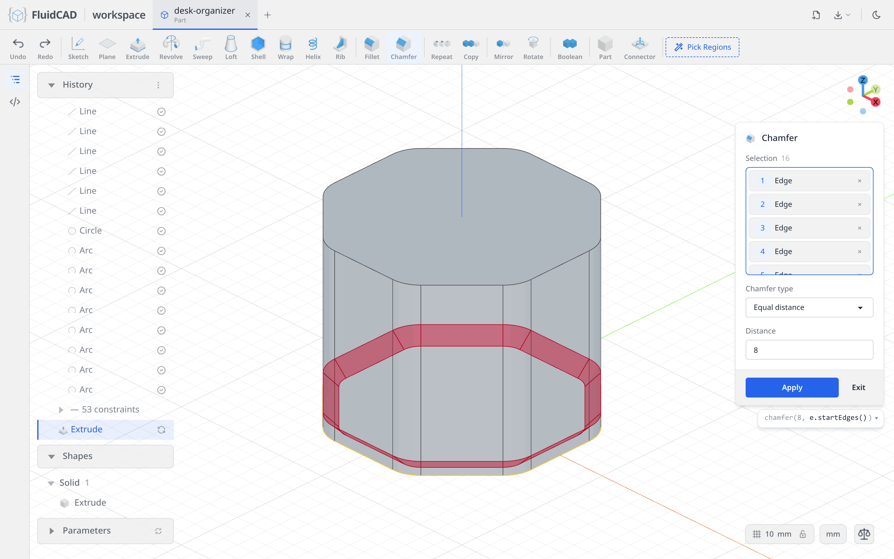
Click Apply.
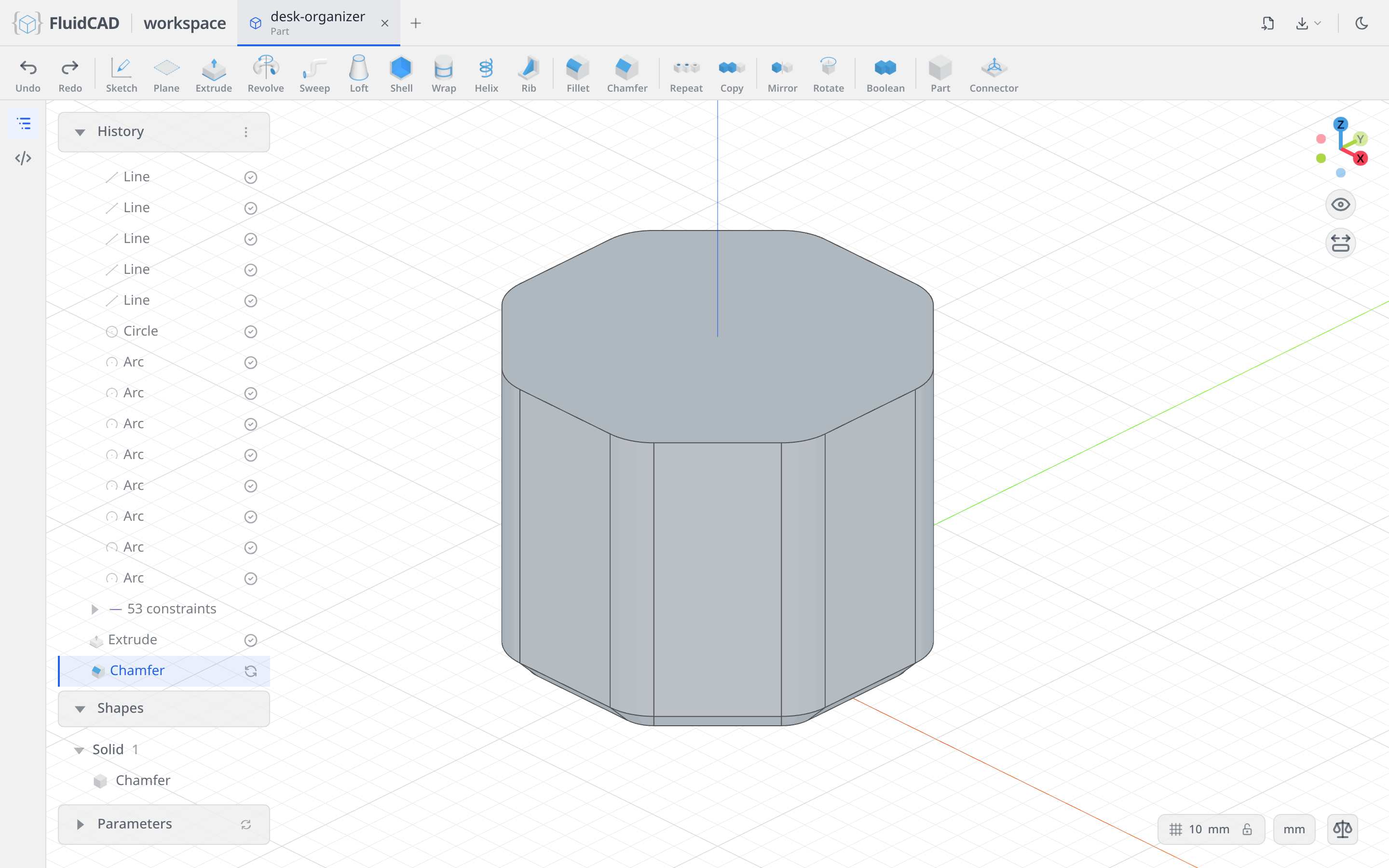
Shell from the top
Click Shell. Click the top face of the prism; it highlights and lands in the Selection slot. Set Thickness to -5. A negative thickness hollows the body inward, keeping the outside dimensions; the picked face is the one that gets removed. The statement reads shell(-5, e.endFaces()).
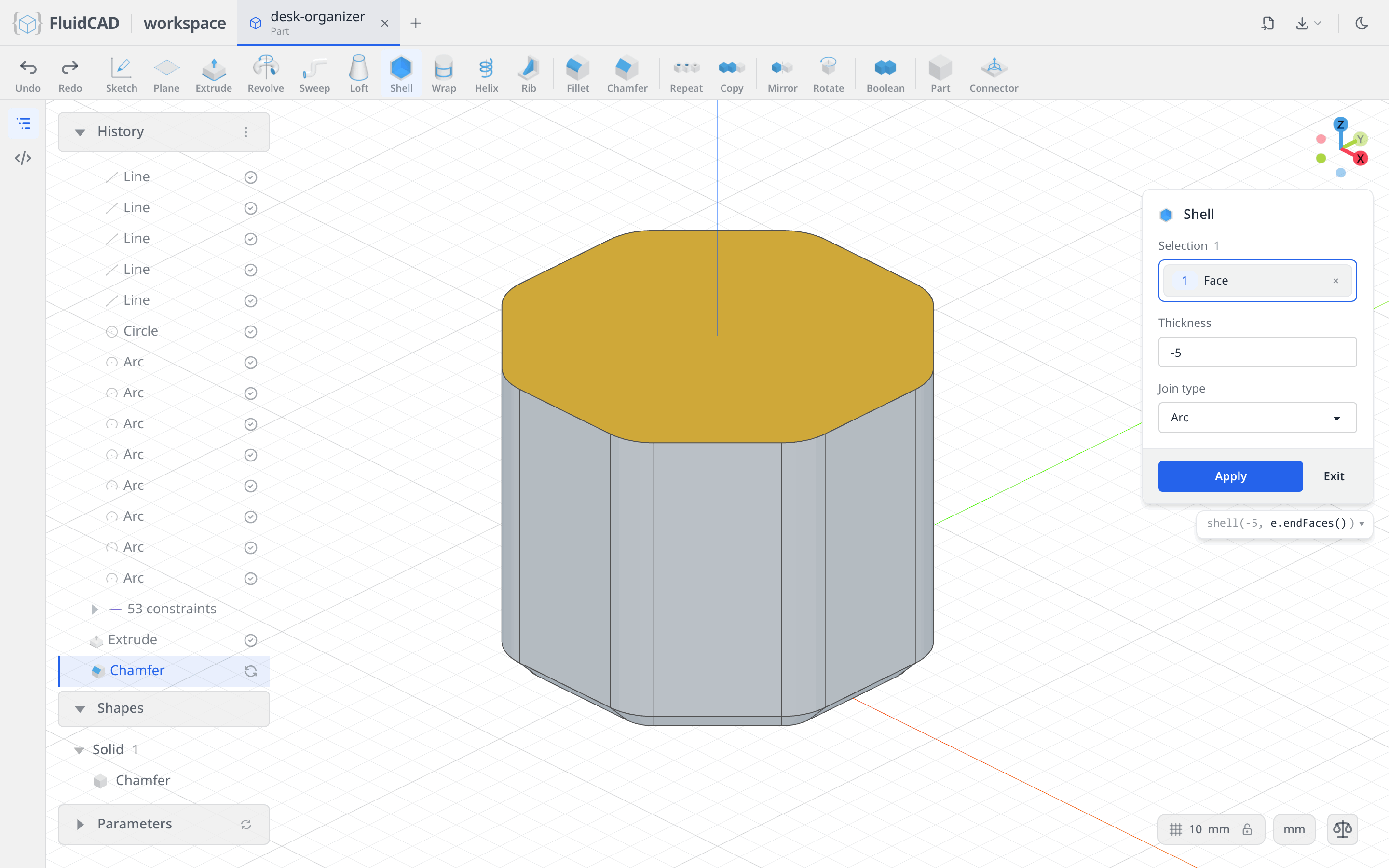
Click Apply. The prism is now a cup with 5 mm walls and a 5 mm floor.
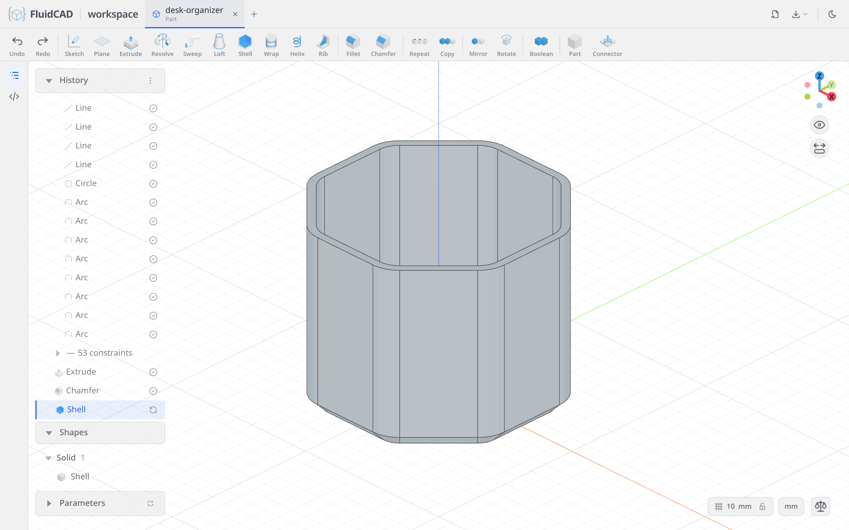
Step 3: Inner square pocket
Sketch a 50 × 50 square
Click Sketch and pick the XY plane again. Because the sketch plane cuts through the cup, Section view clips the walls away so you see the floor as a flat outline.
Pick the Rectangle tool. Click the first corner at (-25, -25), then type 50 for the width, press Enter, type 50 for the height and press Enter again. Typed sizes become dimensions in the sketch rather than guesses.
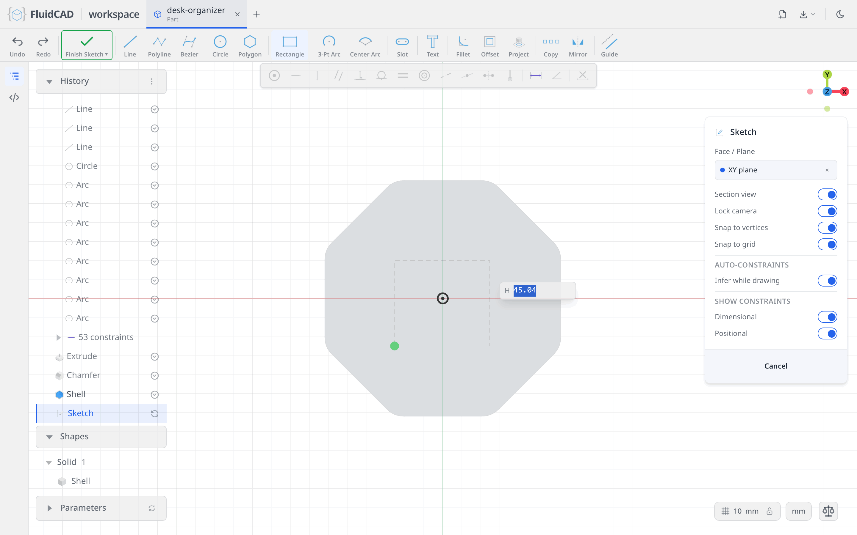
The rectangle arrives as four lines with horizontal, vertical and coincident constraints and the two 50 mm dimensions. It can still slide around as a whole, so click its bottom-left corner point and click Fix on the constraint bar. The pill reads Fully constrained.
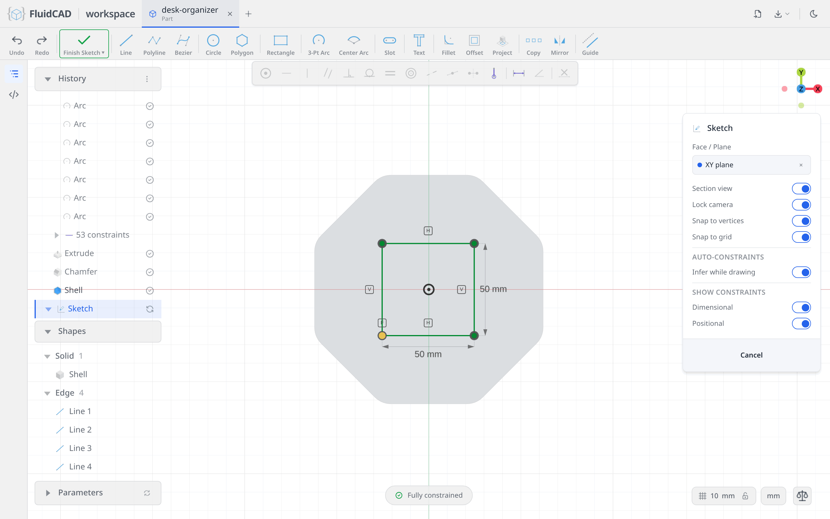
Offset an inner loop
Pick Offset in the sketch toolbar. Click one side of the square and Ctrl+click the other three. Set Distance to -5; the negative value offsets inward. The blue outline is the preview of the second loop.
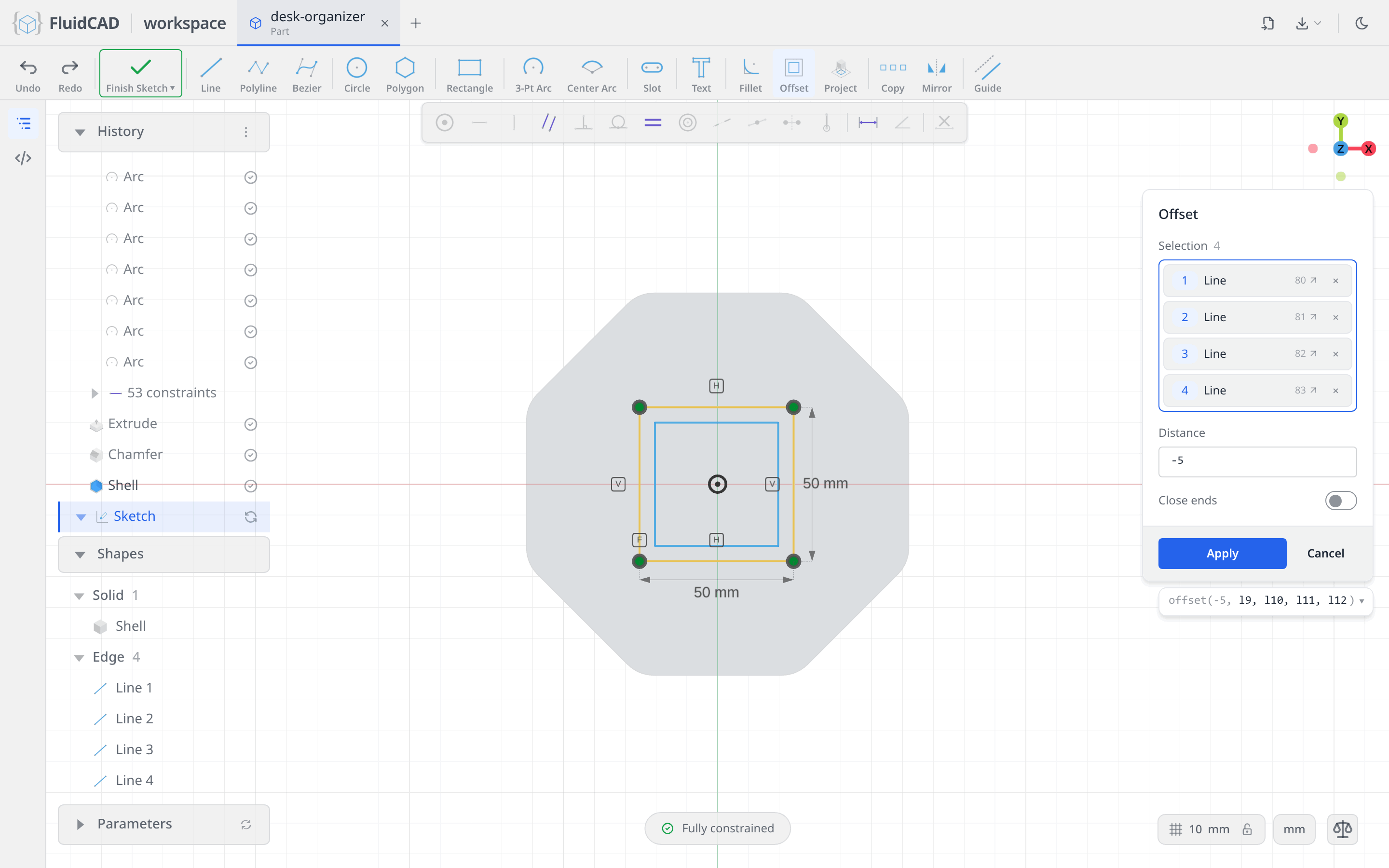
Click Apply. The sketch now holds a closed outer loop and a closed inner loop, which extrudes as a square tube rather than a solid block.
Extrude the column
Click Extrude on the toolbar. Set Distance to 160, taller than the 110 mm cup so the column will stand above the rim. The ghost shows the tube rising from the floor and through the open top.
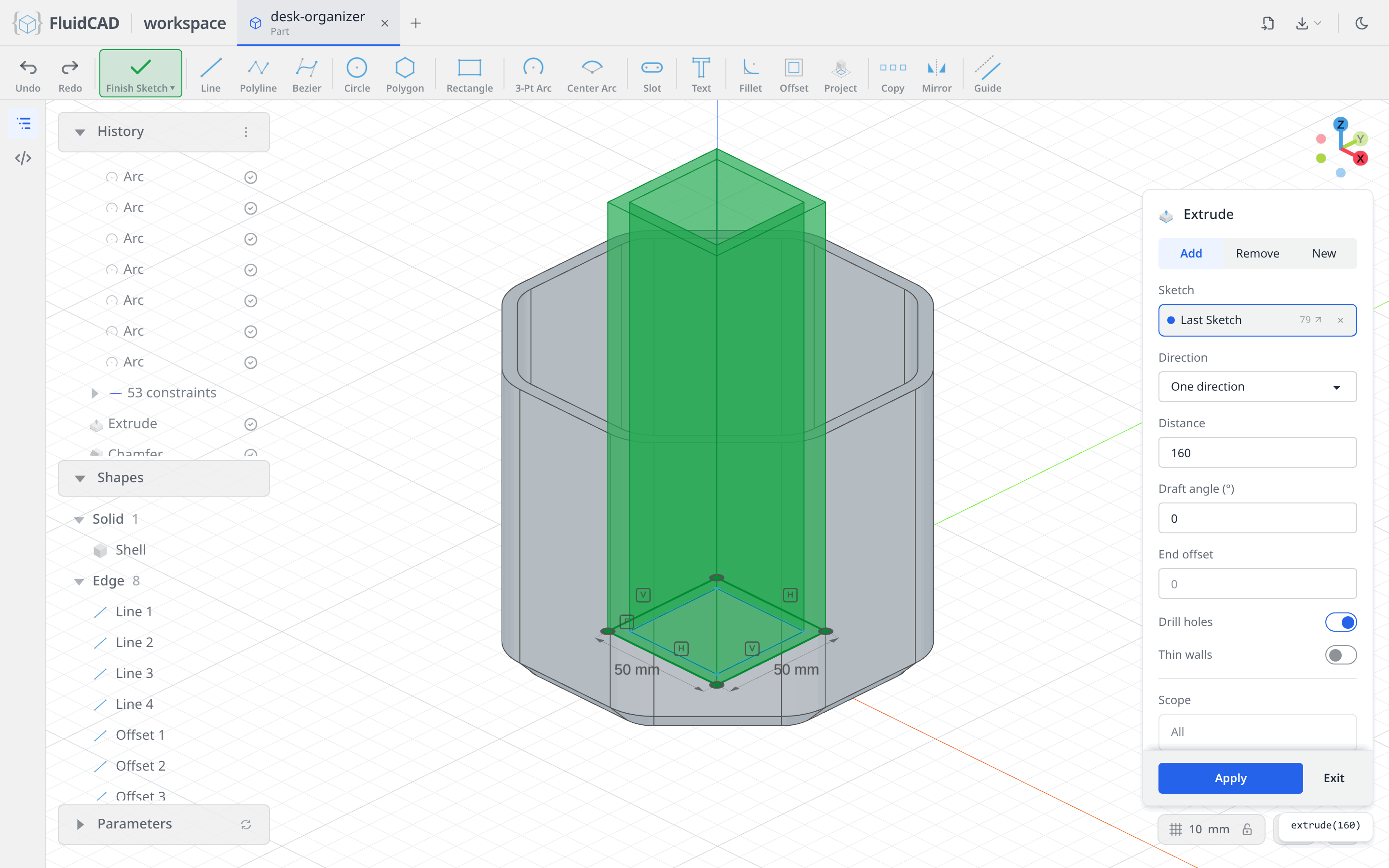
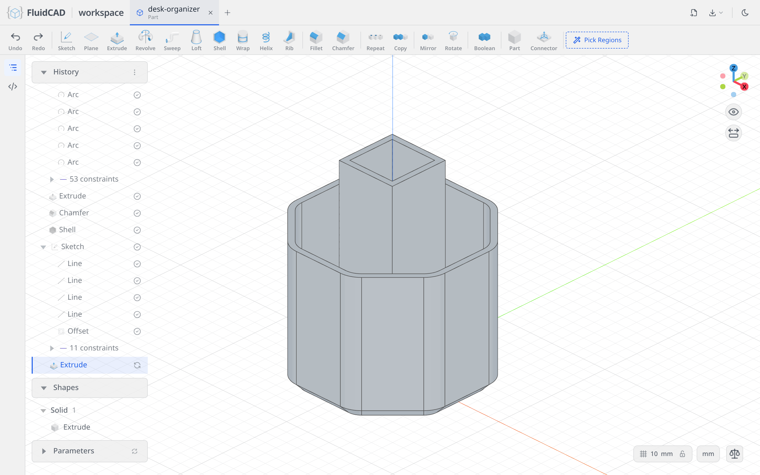
Click Apply. With the Add tab selected the new solid fuses with the cup, so the column and the floor become one body.
Step 4: Add a rib and pattern it around
Make a rotated construction plane
The ribs run diagonally from the column's corners to the outer wall. To sketch one you need a plane on that diagonal. Click Plane in the toolbar, then click the XZ origin plane in the viewport to use it as the base. Set Offset to 0 and the middle Rotation field, the rotation about Y, to 45.
The yellow quad previews the plane, and the statement reads plane('xz', { rotateY: 45 }).
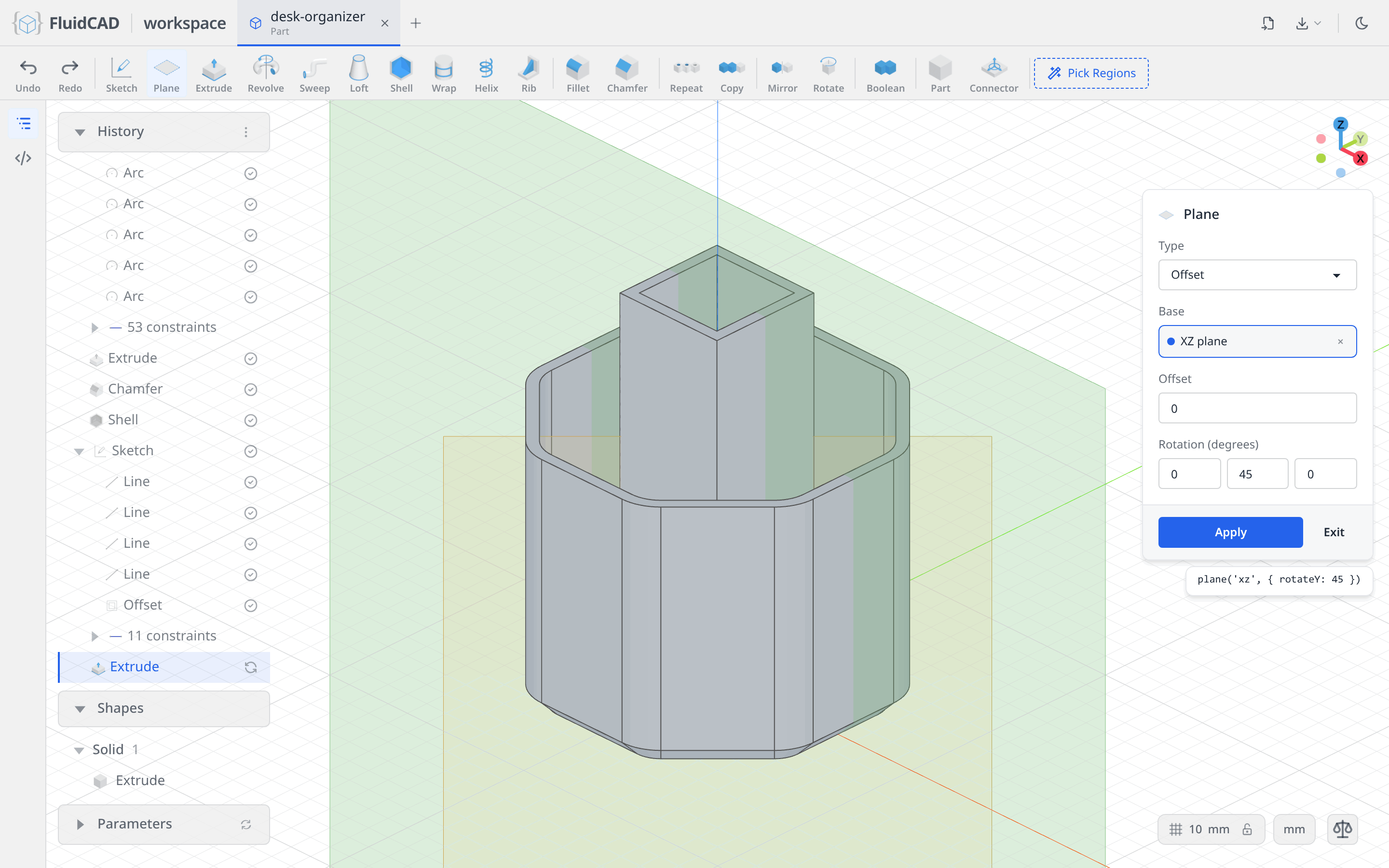
Click Apply. A Plane row is added to History.
Sketch the rib spine
Click Sketch and click the new plane (either its quad in the viewport or its row in the History panel). Section view now slices the model along the diagonal, so you see the column and the outer wall in cross-section.
Pick the Line tool and draw a short line just inside the outer wall, near the top of the cup, angled up and to the right. Then dimension it with the constraint bar:
- Click the line and click Dimension, type
20for its length. - Click the line's start point, Ctrl+click the horizontal axis and click Dimension, type
115. That puts the spine 5 mm above the 110 mm rim. - Click the start point, Ctrl+click the vertical axis, Dimension, type
60. - Click the line, Ctrl+click the horizontal axis and click Angle, type
45.
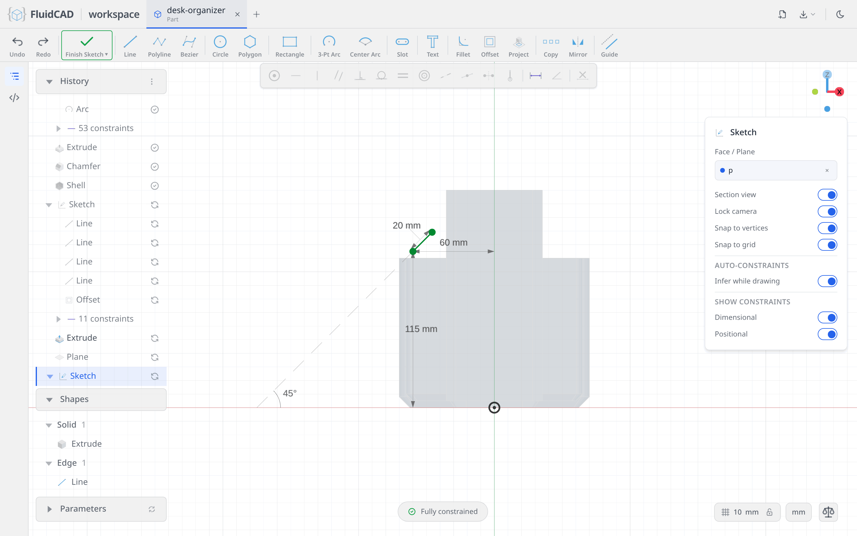
The spine does not need to reach either wall. The rib will be extended to meet them.
Build the rib
Click Rib on the toolbar. Set Thickness to 5, and switch on Parallel to sketch plane and Extend to walls. Parallel grows the rib in the sketch plane, so it stands as a wall rather than being pushed out normal to the plane; Extend stretches the spine until it meets the surrounding solids. The green ghost shows the wall between the column and the outer shell, and the statement reads rib(5).parallel().extend().
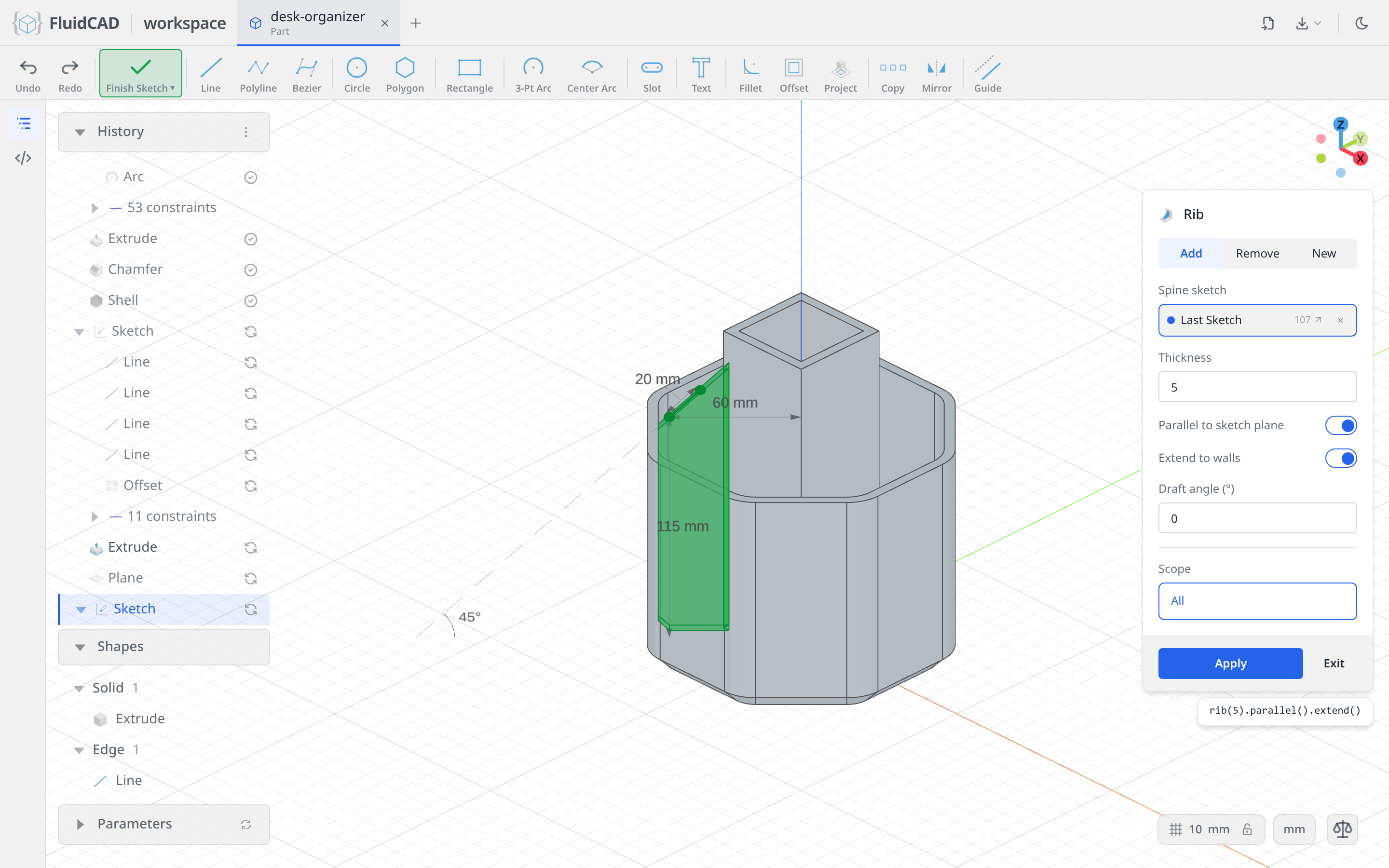
Click Apply.
Pattern it around the Z axis
Click Repeat in the toolbar and set Type to Circular. Repeat takes its targets from the History panel: click the Rib row, and it lands in the Features slot. The axis defaults to World Z axis, which is what you want. Set Total Count to 4 and leave the angle at a total of 360. The ghost shows the three extra ribs.
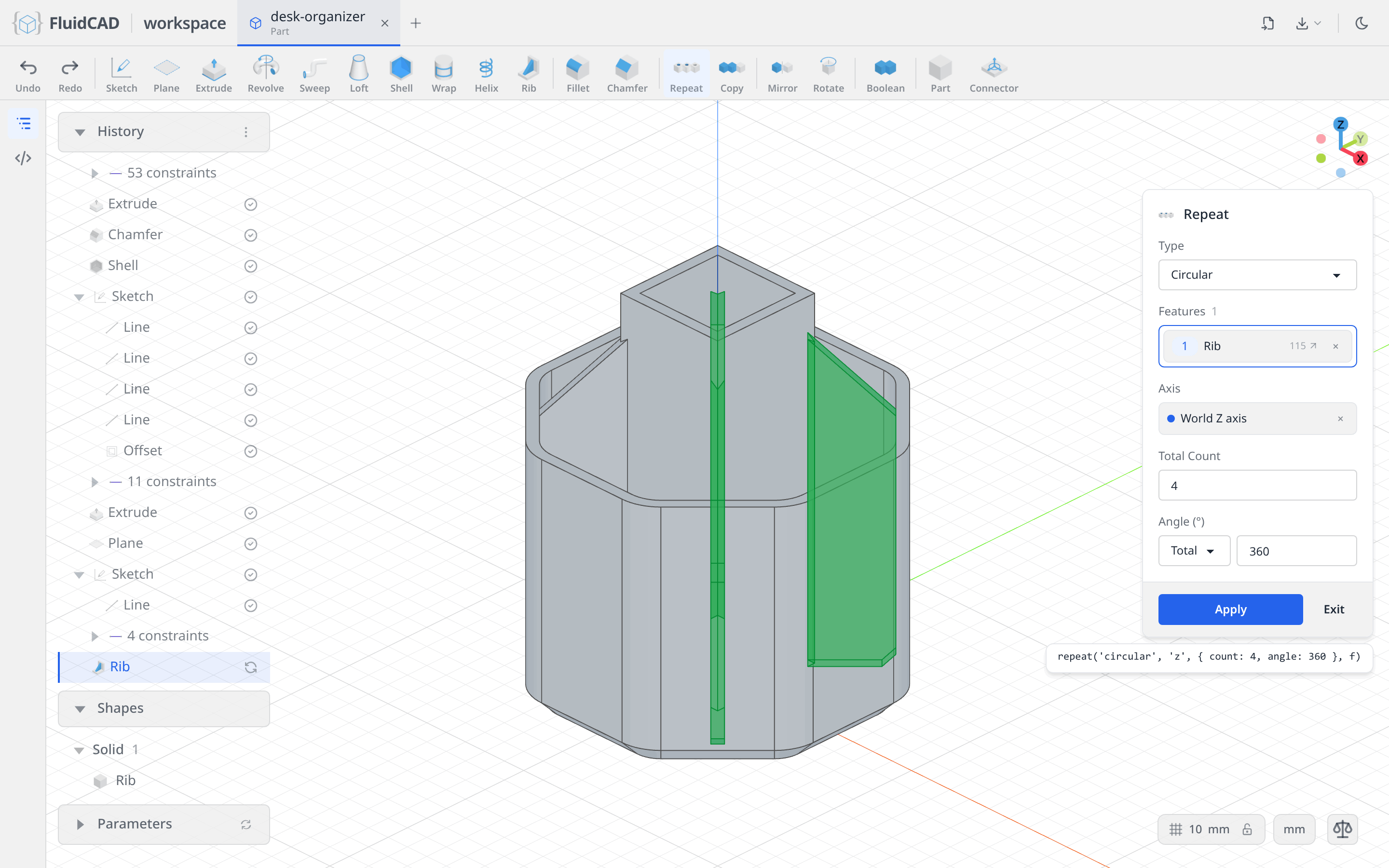
Click Apply. Four rib walls now divide the cup into four compartments.
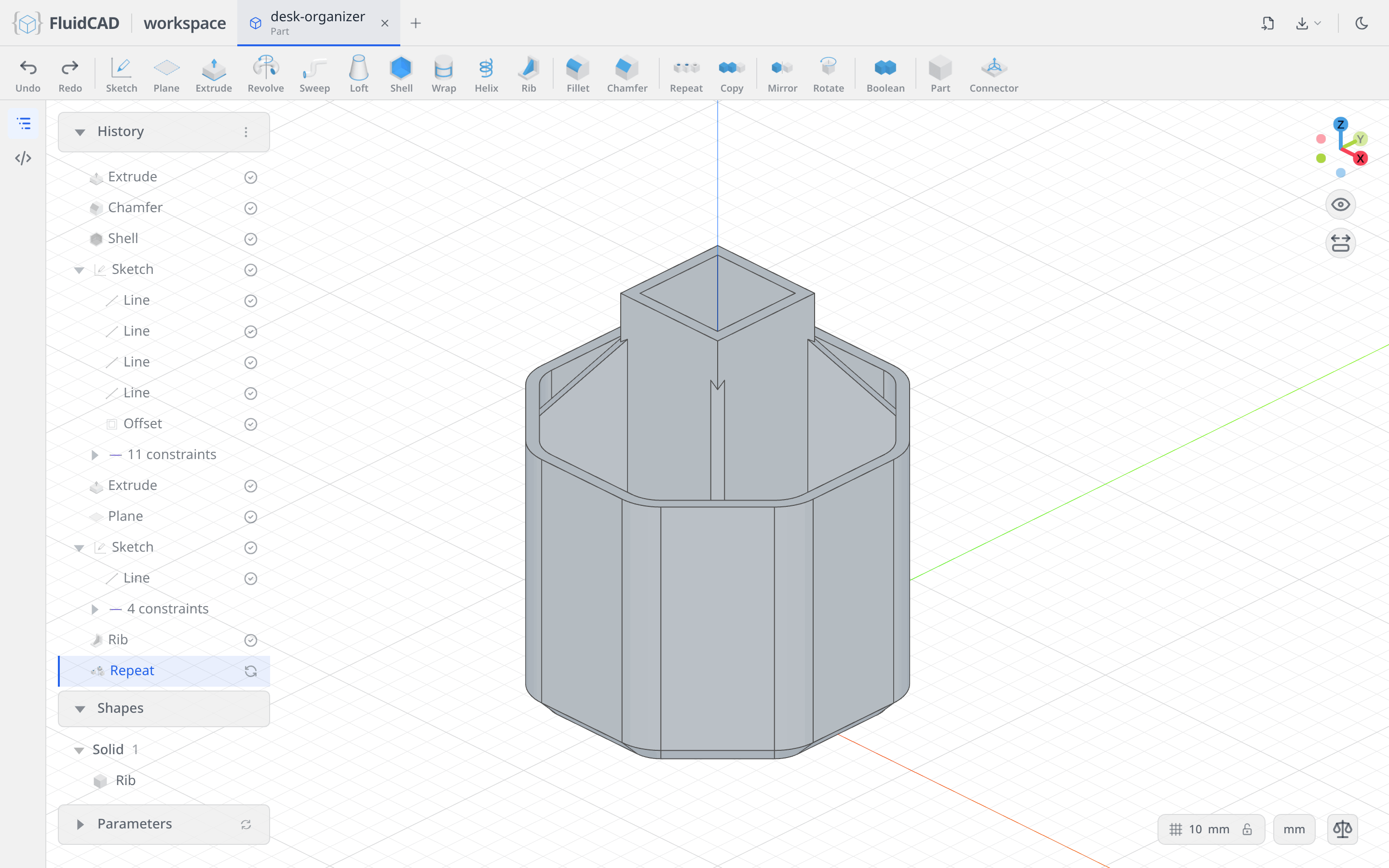
Step 5: Trim the top with a thin revolve cut
Sketch the trim arc
The column and the ribs poke above the rim. You will dome them off by revolving a quarter arc into a hemispherical shell and subtracting it.
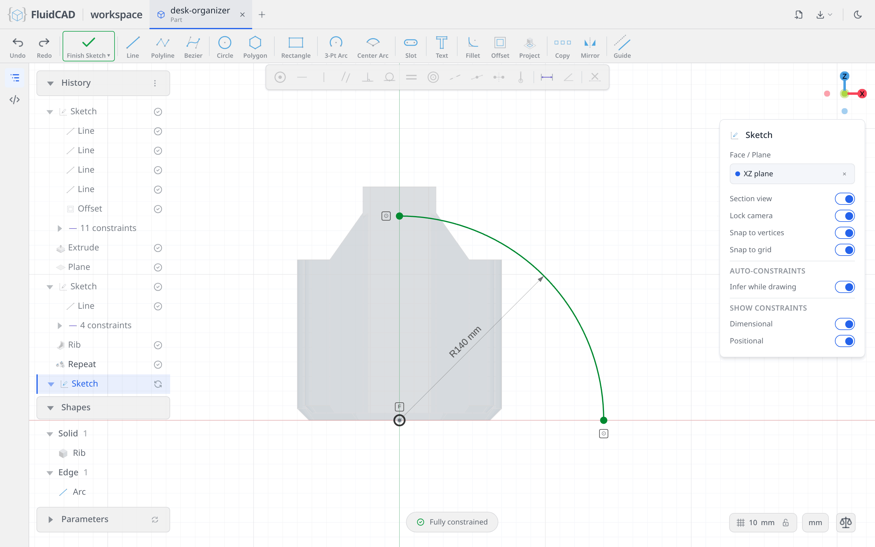
Click Sketch and pick the XZ plane. Pick the Center Arc tool: click the origin for the center, click a point on the horizontal axis to the right for the start, and sweep up to the vertical axis for the end. Constrain it:
- Click the arc's center point and click Fix, so it stays on the revolve axis.
- Click the arc, click Dimension and type
140for the radius. - Click the arc's start point, Ctrl+click the horizontal axis and click Coincident. Do the same for the end point and the vertical axis.
Revolve it as a thin cut
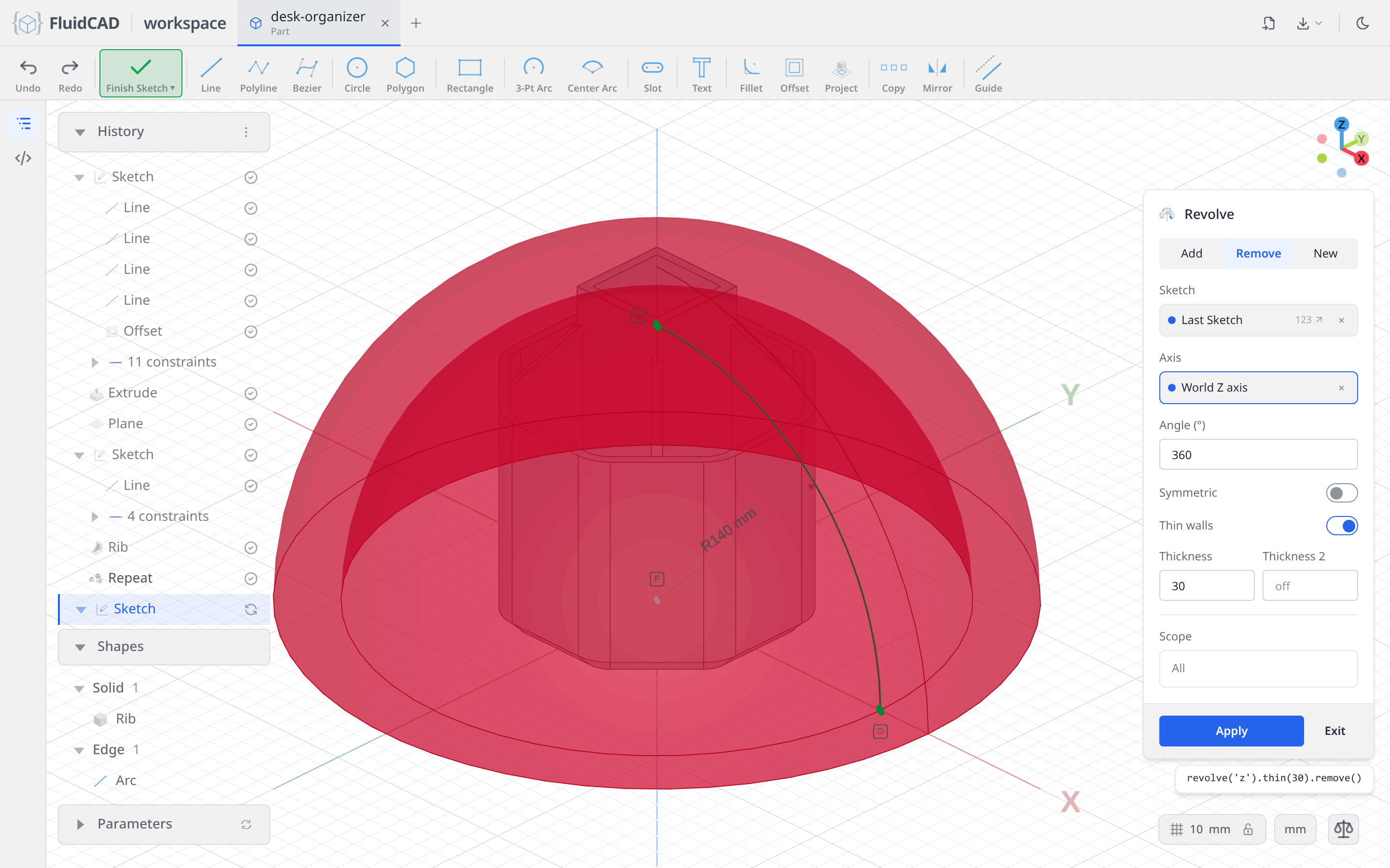
Click Revolve on the toolbar. Select the Remove tab so the revolved shape is subtracted. The axis defaults to World Z axis. Switch on Thin walls and set Thickness to 30: an open arc cannot enclose a solid on its own, so the thin option turns it into a 30 mm thick hemispherical shell. The red ghost is the shell that will be removed; the 30 mm is deliberately generous so it consumes everything above the dome.
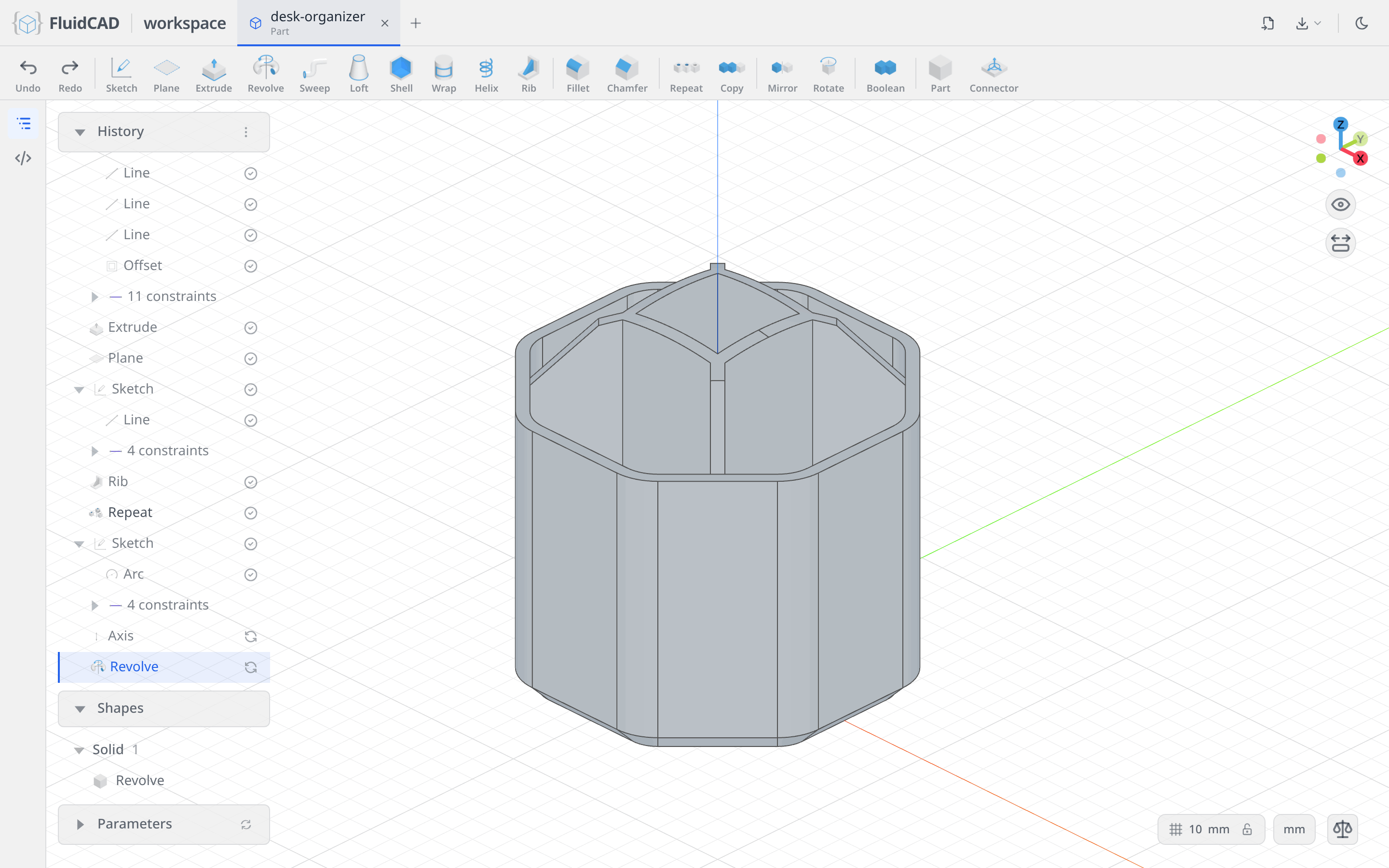
Click Apply. The column's corners are trimmed to a spherical cap and the rib tops follow the same curve.
Full code
Everything above was written into desk-organizer.fluid.js by the dialogs. Open the code editor with the </> button on the left rail or Ctrl+B to read it. The listing below is the same model with tidier names; the coordinates you clicked will differ, but the constraints make the geometry identical.
Show the full code
// @screenshot waitForInput
import { yAxis, origin, circle, breakpoint, plane, sketch, extrude, fillet, chamfer, repeat, rotate, arc, shell, offset, rib, revolve, line, xAxis } from 'fluidcad/core';
import { tangent, diameter, angle, coincident, distance, equal, fix, horizontal, radius, vertical } from "fluidcad/constraints";

sketch('xy', () => {
    const l1 = line([75.77, 0], [53.58, 53.58]);
    const l2 = line([53.58, 53.58], [0, 75.77]);
    const l3 = line([0, 75.77], [-53.58, 53.58]);
    const l4 = line([-53.58, 53.58], [-75.77, 0]);
    const l5 = line([-75.77, 0], [-53.58, -53.58]);
    const l6 = line([-53.58, -53.58], [0, -75.77]);
    const l7 = line([0, -75.77], [53.58, -53.58]);
    const l8 = line([53.58, -53.58], [75.77, 0]);
    const c1 = circle([0, 0], 140).guide();
    const a1 = arc([-20.71, 70], [-34.85, 64.14], [-20.71, 50]);
    const a2 = arc([20.71, 70], [34.85, 64.14], [20.71, 50]).cw();
    const a3 = arc([-64.14, 34.85], [-70, 20.71], [-50, 20.71]);
    const a4 = arc([-70, -20.71], [-64.14, -34.85], [-50, -20.71]);
    const a5 = arc([-34.85, -64.14], [-20.71, -70], [-20.71, -50]);
    const a6 = arc([20.71, -70], [34.85, -64.14], [20.71, -50]);
    const a7 = arc([64.14, -34.85], [70, -20.71], [50, -20.71]);
    const a8 = arc([70, 20.71], [64.14, 34.85], [50, 20.71]);
    equal(l1, l2, l3, l4, l5, l6, l7);
    tangent(l1, c1);
    tangent(l2, c1);
    tangent(l3, c1);
    tangent(l4, c1);
    tangent(l5, c1);
    tangent(l6, c1);
    tangent(l7, c1);
    tangent(l8, c1);
    angle(l1, l2, 45);
    diameter(c1, 140);
    coincident(c1.center(), origin());
    horizontal(l3);
    coincident(a1.start(), l3.end());
    coincident(a1.end(), l4.start());
    tangent(l3, a1);
    tangent(a1, l4);
    coincident(a2.start(), l3.start());
    coincident(a2.end(), l2.end());
    tangent(l3, a2);
    tangent(a2, l2);
    coincident(a3.start(), l4.end());
    coincident(a3.end(), l5.start());
    tangent(l4, a3);
    tangent(a3, l5);
    coincident(a4.start(), l5.end());
    coincident(a4.end(), l6.start());
    tangent(l5, a4);
    tangent(a4, l6);
    coincident(a5.start(), l6.end());
    coincident(a5.end(), l7.start());
    tangent(l6, a5);
    tangent(a5, l7);
    coincident(a6.start(), l7.end());
    coincident(a6.end(), l8.start());
    tangent(l7, a6);
    tangent(a6, l8);
    coincident(a7.start(), l8.end());
    coincident(a7.end(), l1.start());
    tangent(l8, a7);
    tangent(a7, l1);
    coincident(a8.start(), l1.end());
    coincident(a8.end(), l2.start());
    tangent(l1, a8);
    tangent(a8, l2);
    radius(a1, 20);
    equal(a1, a2);
    equal(a1, a3);
    equal(a1, a4);
    equal(a1, a5);
    equal(a1, a6);
    equal(a1, a7);
    equal(a1, a8);
});

const outer = extrude(110);

chamfer(8, outer.startEdges())

shell(-5, outer.endFaces())

sketch('xy', () => {
    const sg1 = line([-25, -25], [25, -25]);
    const sg2 = line([25, -25], [25, 25]);
    const sg3 = line([25, 25], [-25, 25]);
    const sg4 = line([-25, 25], [-25, -25]);
    coincident(sg1.end(), sg2.start());
    coincident(sg2.end(), sg3.start());
    coincident(sg3.end(), sg4.start());
    coincident(sg4.end(), sg1.start());
    horizontal(sg1);
    vertical(sg2);
    horizontal(sg3);
    vertical(sg4);
    fix(sg1.start(), [-25, -25]);
    distance(sg1.start(), sg1.end(), 50);
    distance(sg2.start(), sg2.end(), 50);

    offset(-5);
});

extrude(160);

const p = plane("front", { rotateY: 45 })

sketch(p, () => {
    const l9 = line([-60.61, 110], [-46.46, 124.14]);
    distance(l9.start(), xAxis(), 115);
    angle(xAxis(), l9, 45);
    distance(l9.start(), l9.end(), 20);
    distance(l9.start(), yAxis(), 60);

});

rib(5).parallel().extend();

repeat("circular", "z", {
    count: 4,
    angle: 360
})

sketch('xz', () => {
    const a = arc([140, 0], [51.22, 130.29], [0, 0]);
    fix(a.center(), [0, 0]);
    radius(a, 140);
    coincident(a.start(), xAxis());
    coincident(a.end(), yAxis());
});

revolve('z').thin(30).remove()
What you practiced
- Starting a sketch from the Sketch tool and an origin plane, with section view slicing the model at the sketch plane
- Polygon with a typed diameter and side count, and what it emits: a guide circle, tangent and equal sides, and an angle between neighbors
- Horizontal, Fix, Dimension, Angle and Coincident from the constraint bar, and reading the DOF pill until a sketch is fully constrained
- Sketch Fillet on a run of sides, which swaps every corner for a tangent arc with one shared radius
- Extrude, Rib and Revolve applied straight from the toolbar to the open sketch, and the live ghost preview in each dialog
- Chamfer with a double-click to pick a whole edge group, and Shell with a negative thickness and a picked face to open
- Rectangle with typed sizes and Fix to pin a corner, then Offset for an inner loop
- Plane with a rotation about an axis, and dimensioning a sketch against its own axes
- Rib with parallel and extend, and Repeat picking its targets from the History panel
- Revolve on the Remove tab with Thin walls, as a trim cut