Building a Drafted Box
Build a shelled box with a tapered central pipe and four support ribs, based on the original design by Too Tall Toby. You'll use the workspace tools throughout: a centered Rectangle, offset planes, drafted extrusions and a cut, two fillets, Shell, and a circular Repeat. The full code at the end keeps the tool-generated operations with tidier names.
Before you start
Open a workspace and click + in the top bar to create drafted-box.fluid.js. Click the unit chip at the bottom right and choose in (inches) before drawing. All lengths below are in inches; angles are in degrees. The file declares unit('in'), so it also opens correctly in a millimeter project.
- Ctrl+click adds to a selection. Right-click opens the available edge or face groups.
- The sketch's DOF pill reads Fully constrained when nothing is free to move.
- Each dialog previews the statement it will write. Apply or Enter commits it; Exit / Escape cancels it.
- Use Fit to view to frame the model. In a sketch, N looks straight down its plane.
Step 1: Draft and round the base
Put the footprint at the rim height
Click Plane. Leave Type on Offset, select the XY datum plane, and enter 1.5 for Offset. Leave all rotations at 0. The preview is parallel to XY, 1.5 inches above it; the statement reads plane('xy', 1.5).
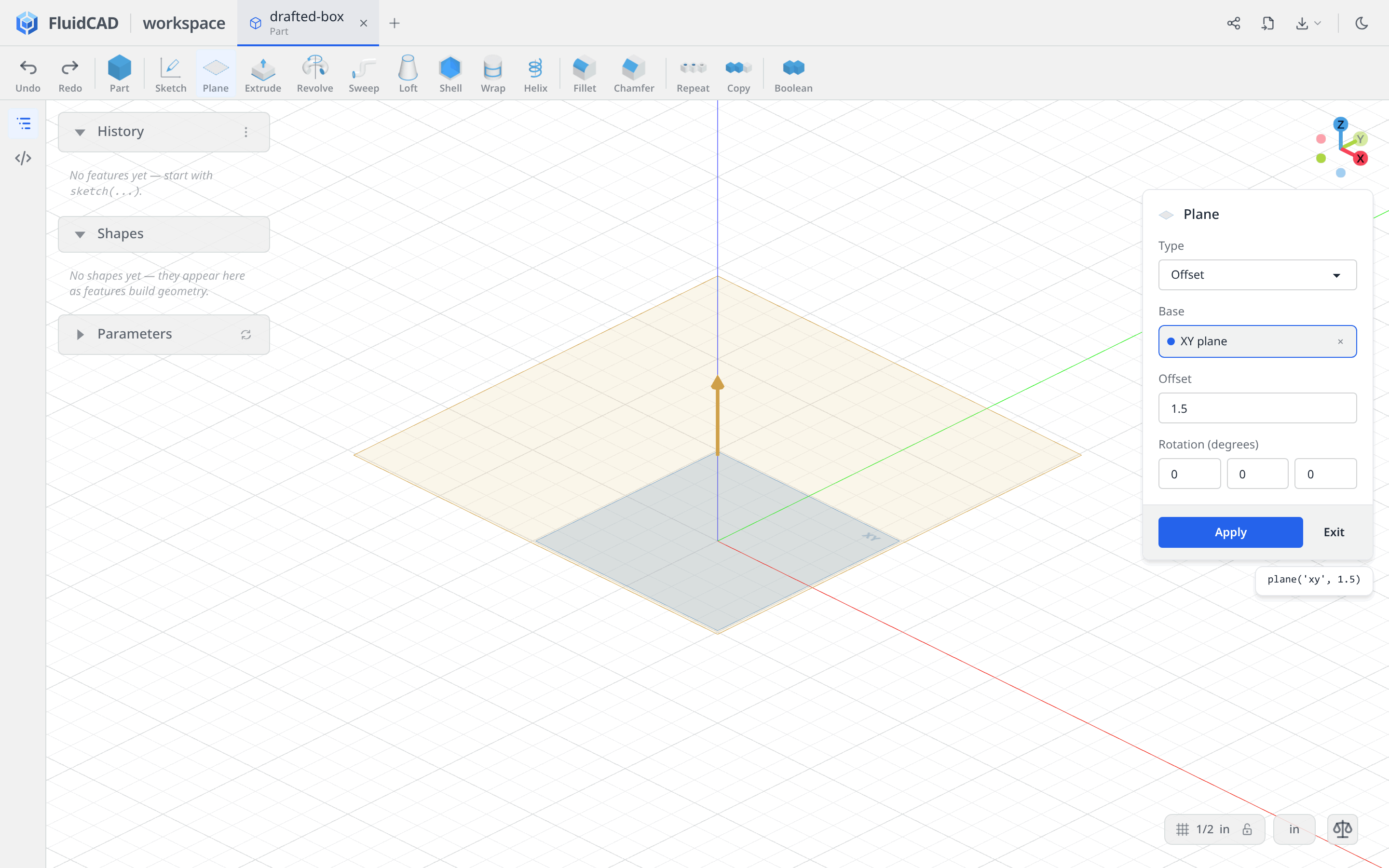
Click Apply, then Sketch and select the new plane in History.
Draw a centered rectangle
Choose Rectangle. Enable Centered and leave Rounded off: the corners will be rounded after drafting the solid.
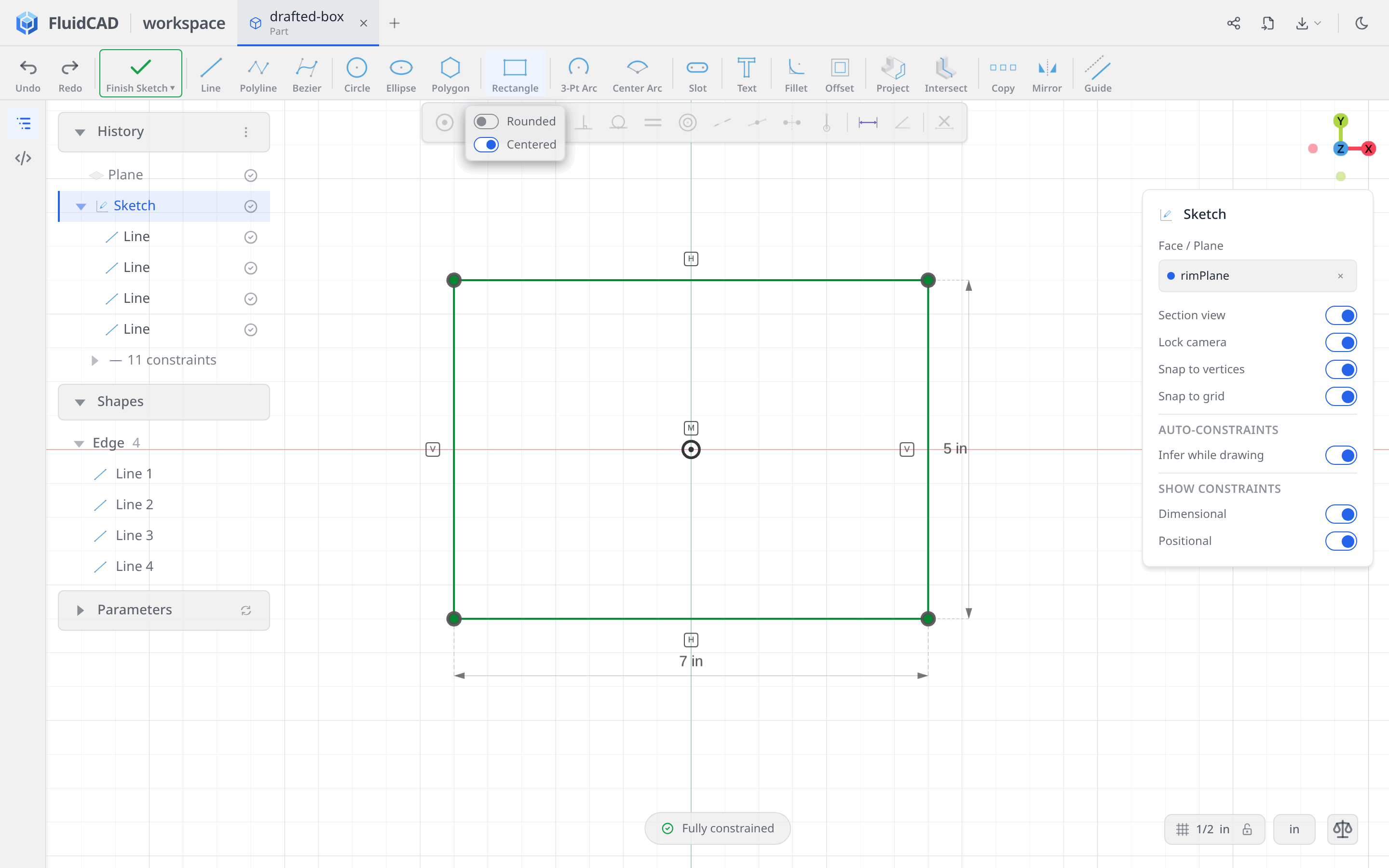
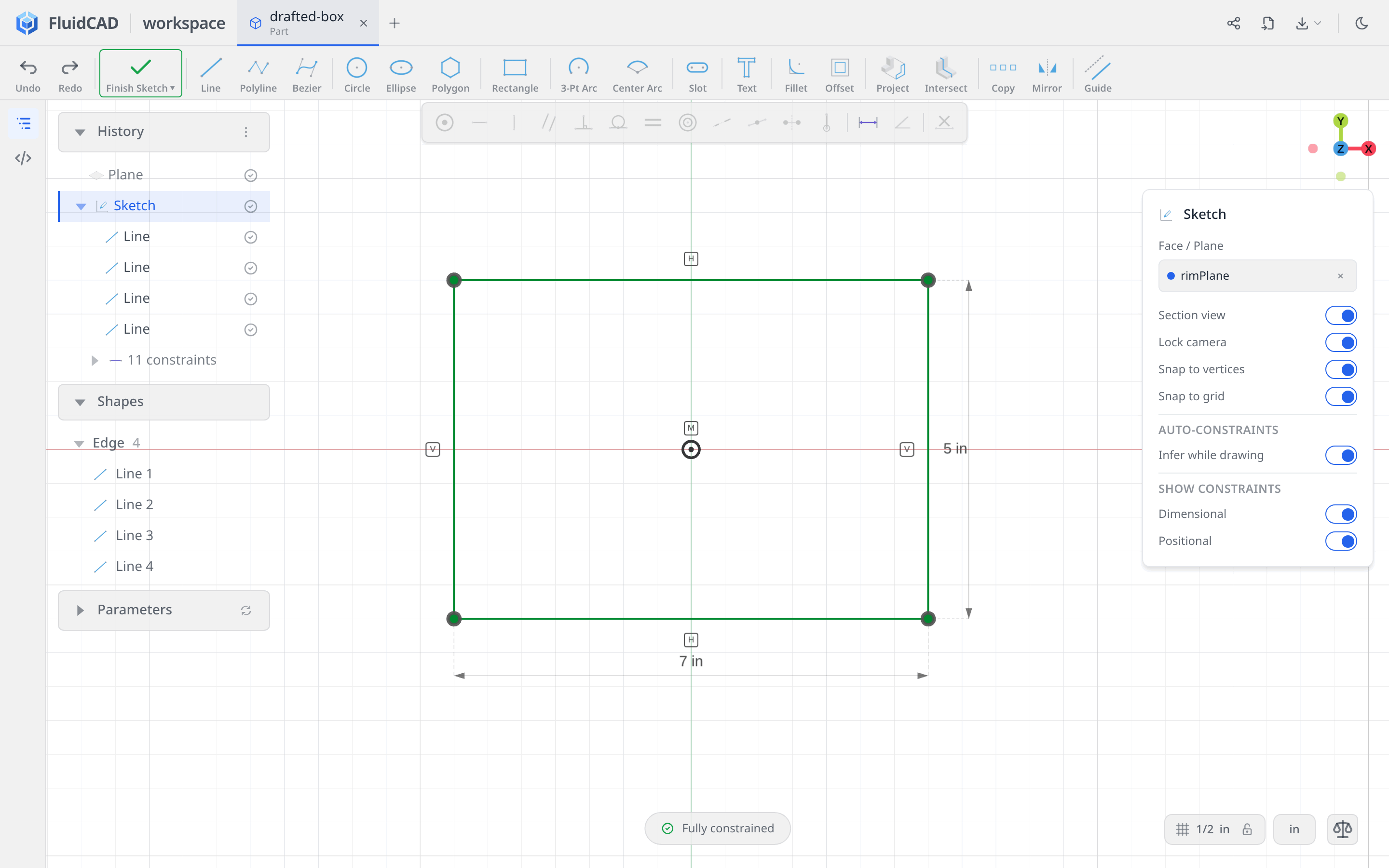
Click the origin for the center, then move up and right. Type 7 for W, press Enter, then 5 for H and Enter. Press Escape to leave the tool.
The Rectangle tool writes the horizontal, vertical, corner-coincidence, width, height, and center constraints. The pill should read Fully constrained.
Extrude downward with draft
Click Extrude on the toolbar. Leave Add and One direction selected. Enter -1.5 for Distance and -8 for Draft angle (°). Leave Thin walls off.
The green preview extends from the rim plane down to XY. Its lower footprint is smaller than the 7 × 5 inch top. The statement reads extrude(-1.5).draft(-8).
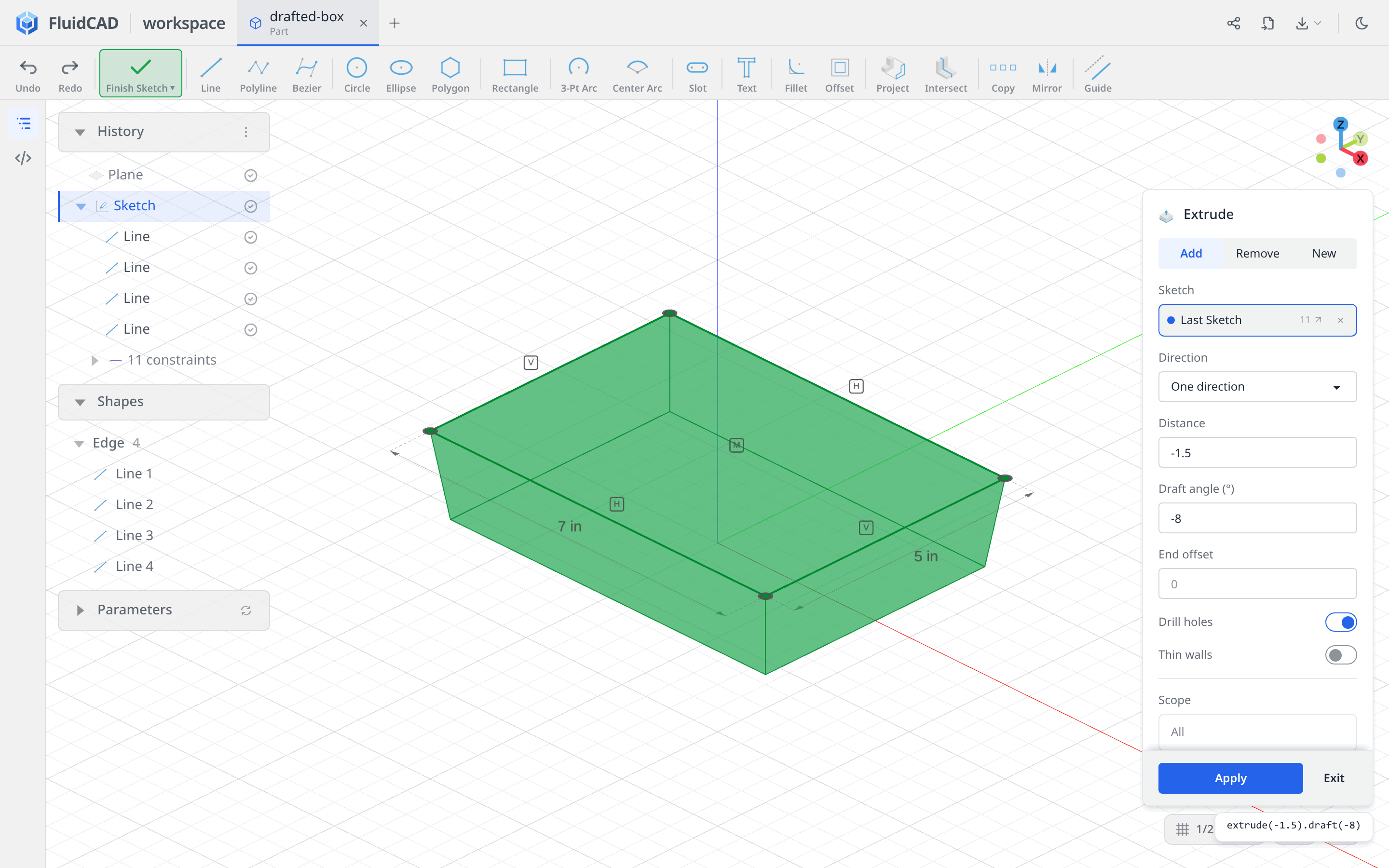
Click Apply.
Round the four corners
Click Fillet, click a sloping corner edge, then double-click that edge to expand to the extrusion's four side edges. Check that the dialog lists four Edge entries, not faces. Set Radius to 0.75. The statement reads fillet(0.75, base.sideEdges()); generated variable names may differ.
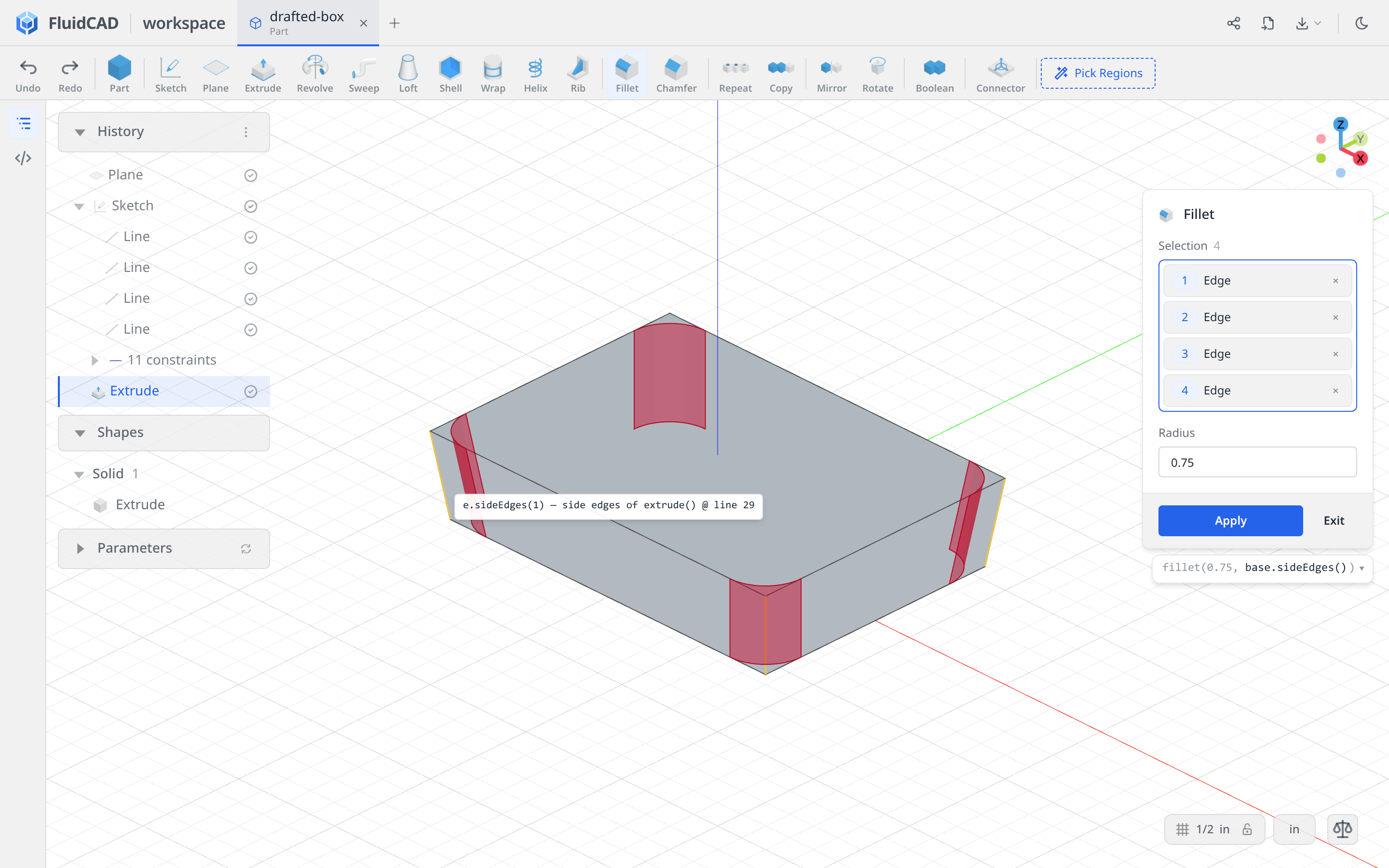
Click Apply.
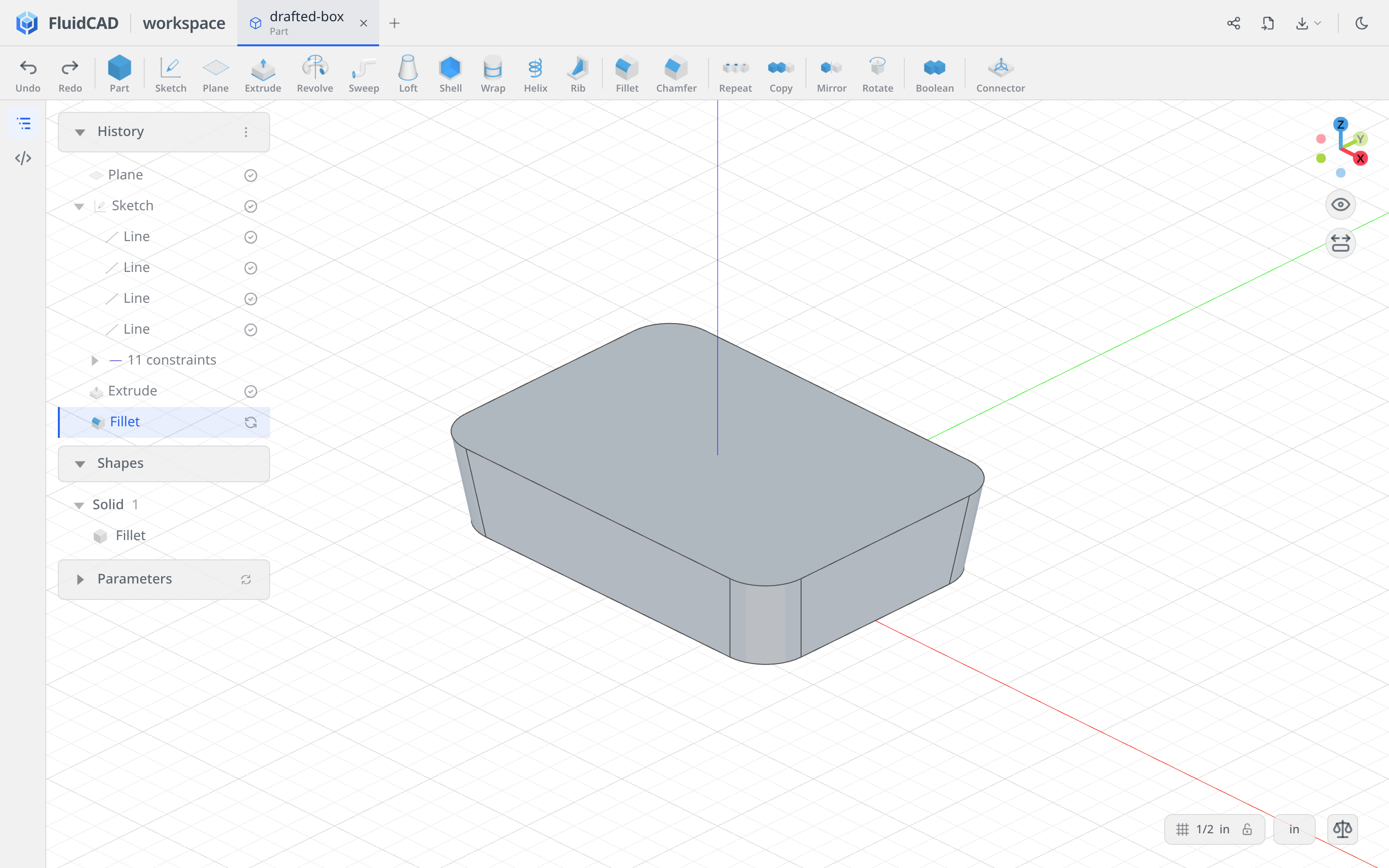
Round the underside rim
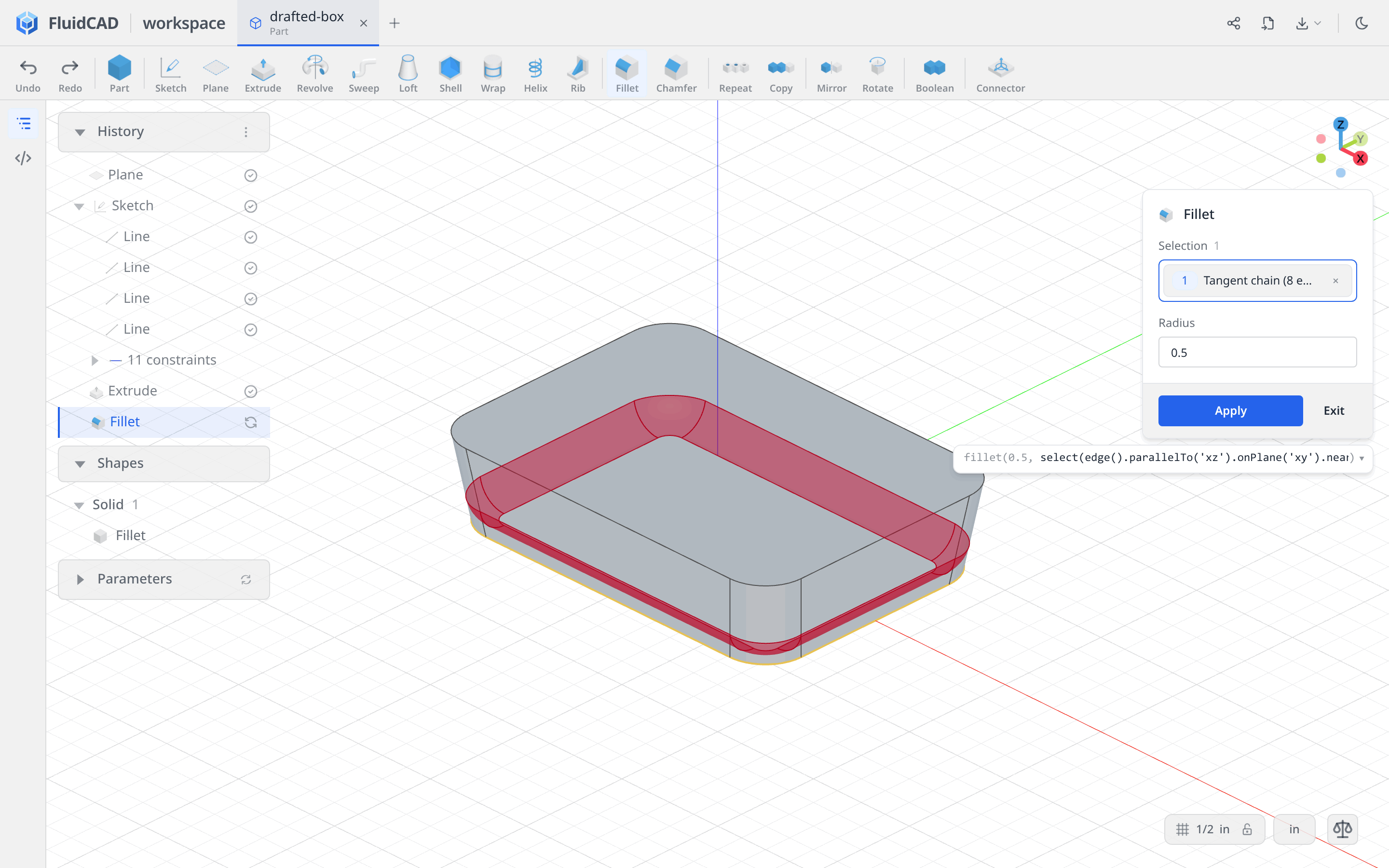
Click Fillet again. Right-click a lower perimeter edge where the outside wall meets the flat underside, and choose Tangent Edges (8). Set Radius to 0.5.
The highlighted chain must follow the bottom rim on XY, not the upper rim at Z = 1.5. It includes the four straight edges and four corner arcs. The statement uses an edge selection ending in .withTangents().
Click Apply.
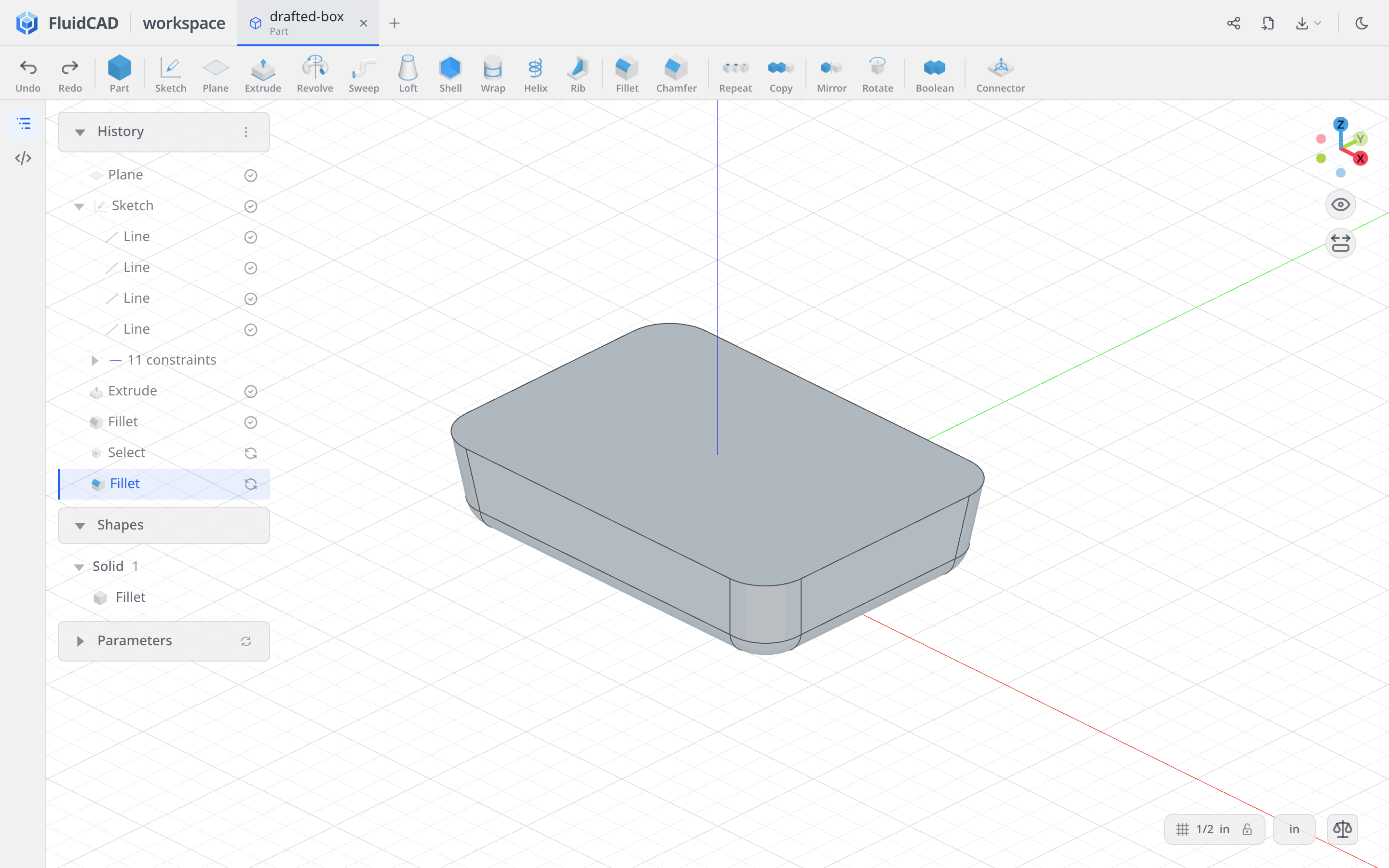
Step 2: Open the box with Shell
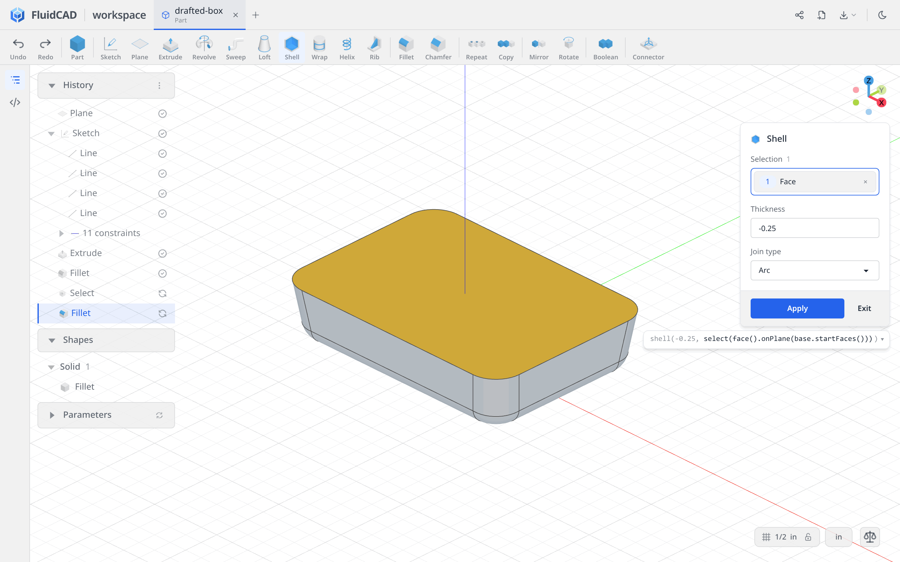
Click Shell and select the large top face. Enter -0.25 for Thickness, leaving Join type on Arc. Negative thickness hollows inward; the selected face becomes the opening. The statement reads shell(-0.25, select(face().onPlane(base.startFaces()))).
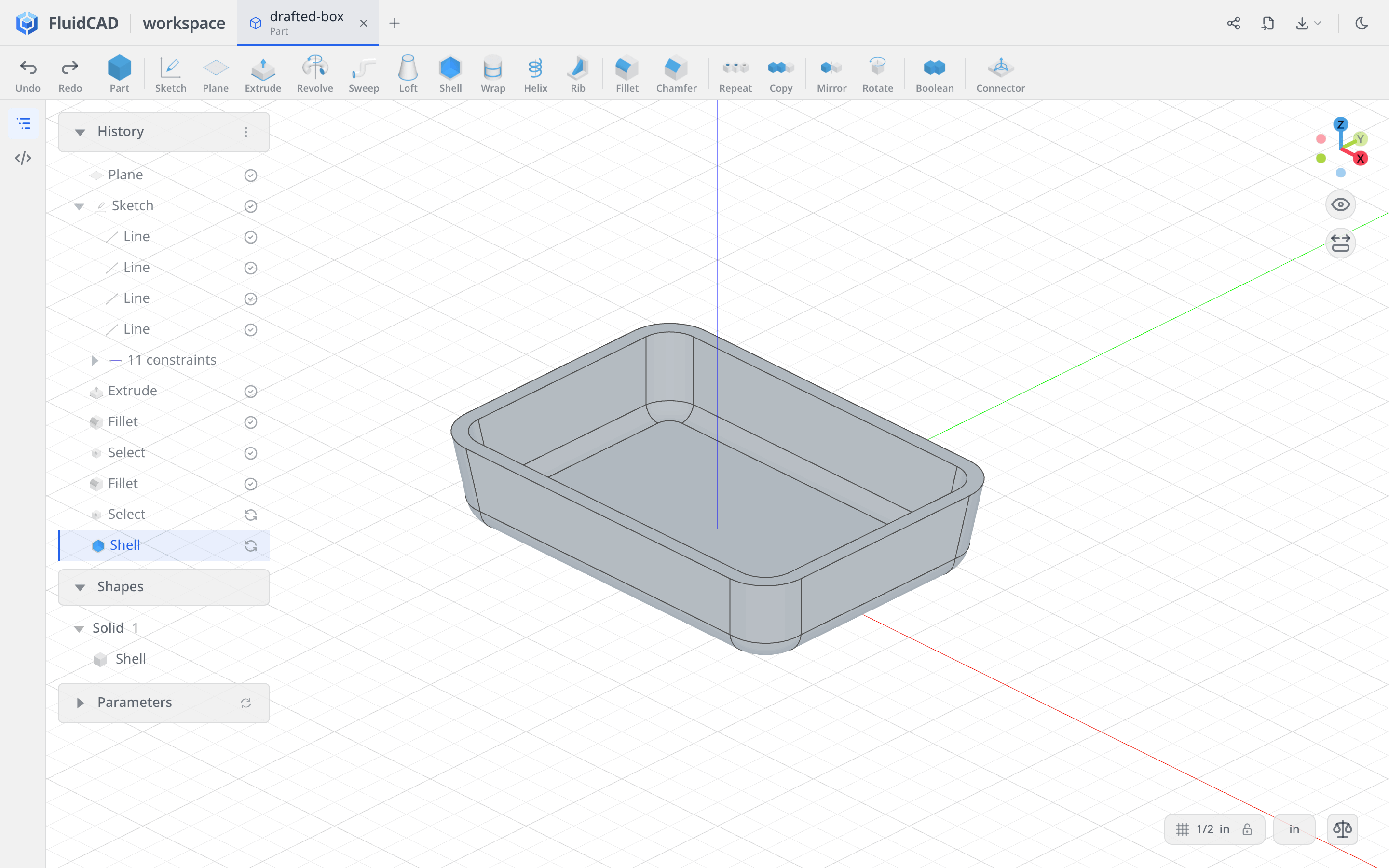
Click Apply. The box retains its outer dimensions, with quarter-inch walls and floor.
Step 3: Add the drafted pipe
Make a plane above the box
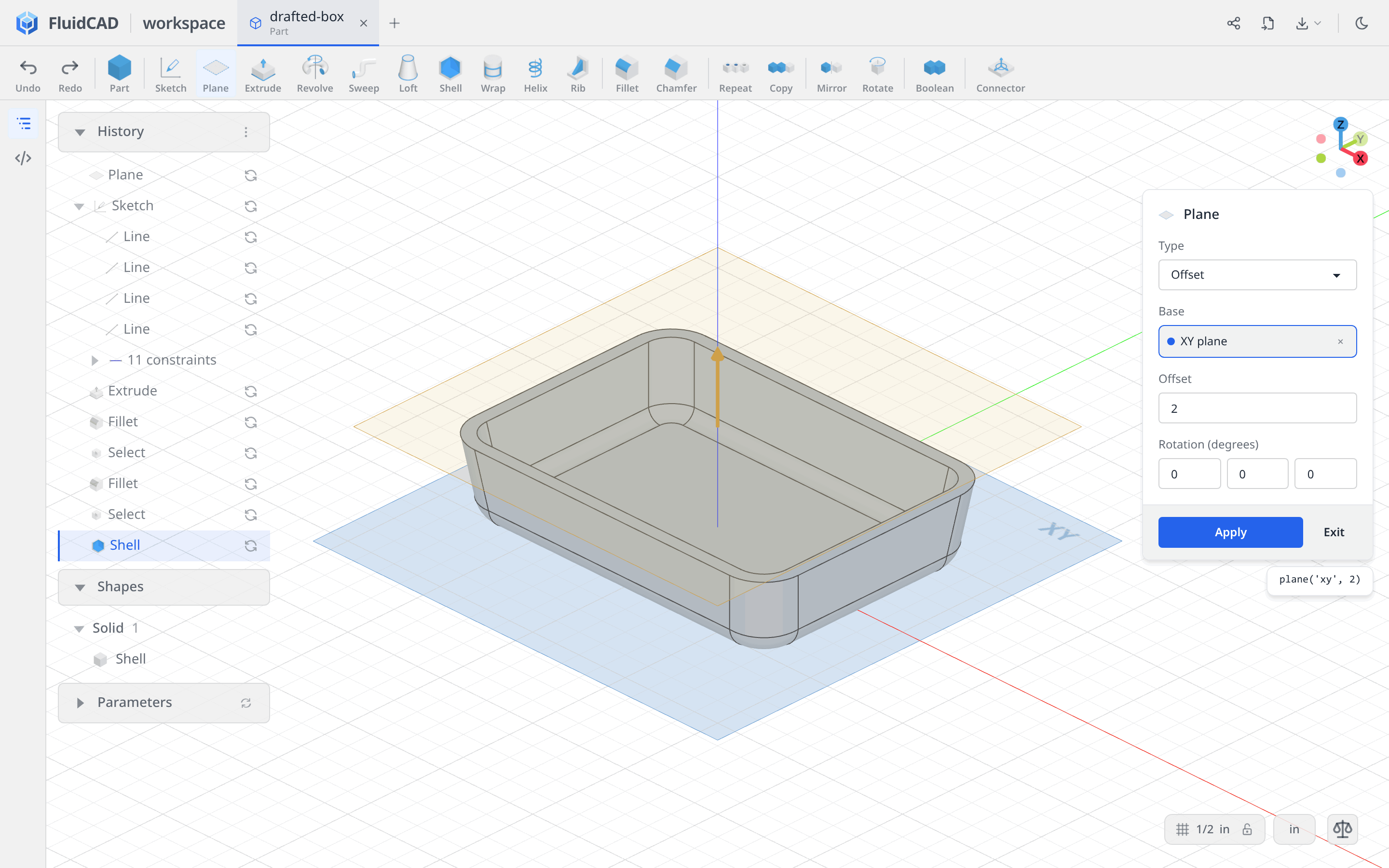
Click Plane, choose the XY datum plane as Base, and set Offset to 2. Check the base chip: this offset is measured from XY, not from the box rim. The new plane sits half an inch above the opening.
Click Apply, then Sketch and select the new plane in History.
Draw the pipe's outer circle
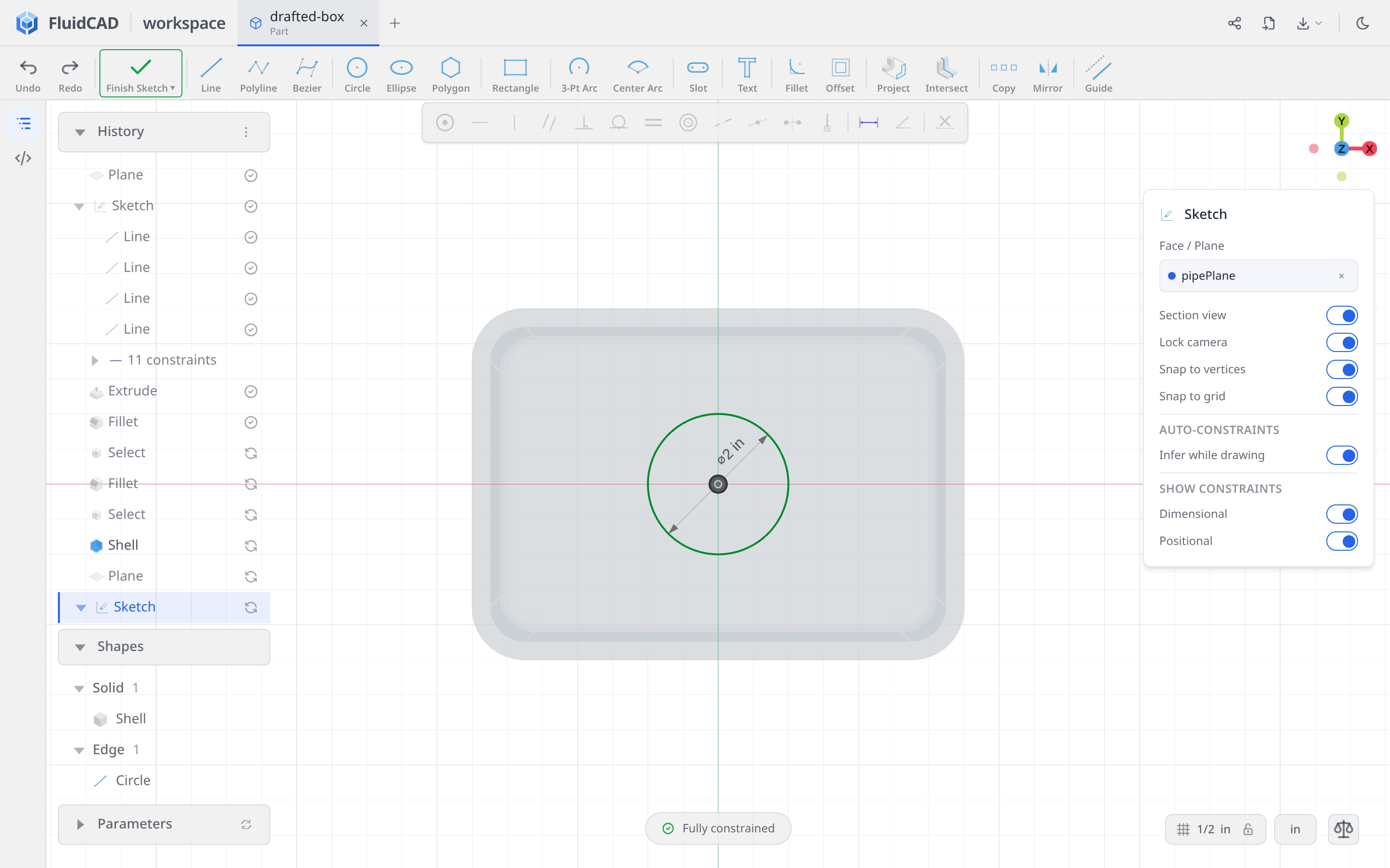
Choose Circle, click the origin, and type 2 for the diameter, then Enter. Press Escape. Snapping the center to the origin and typing the diameter fully constrains the circle.
Extrude into the floor
Click Extrude on the toolbar, leave Add selected, and set Distance to -2 and Draft angle (°) to 8. The preview flares outward toward the floor and overlaps it, joining the pipe to the box. The statement reads extrude(-2).draft(8).
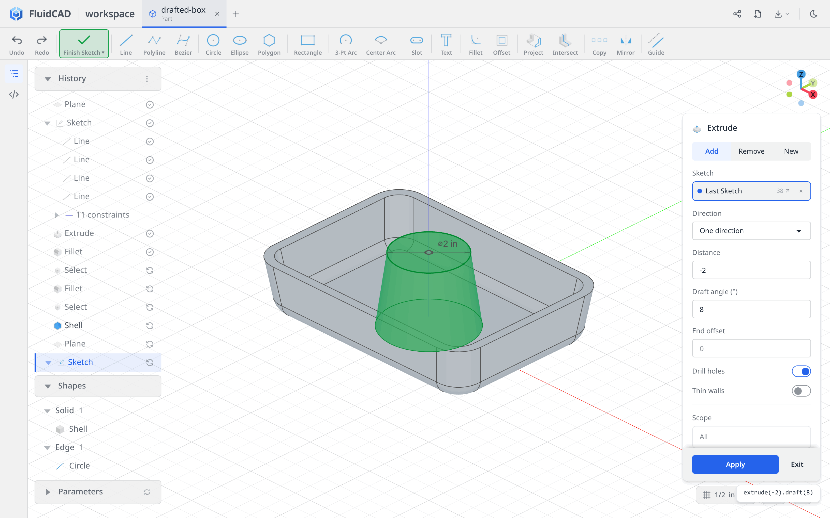
Click Apply.
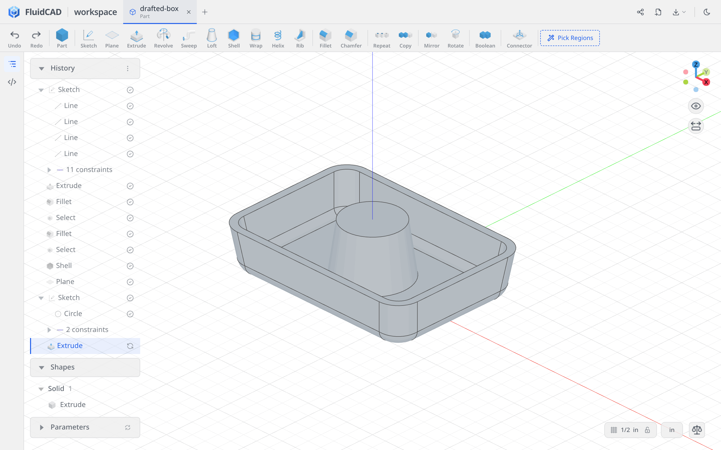
Step 4: Bore the pipe
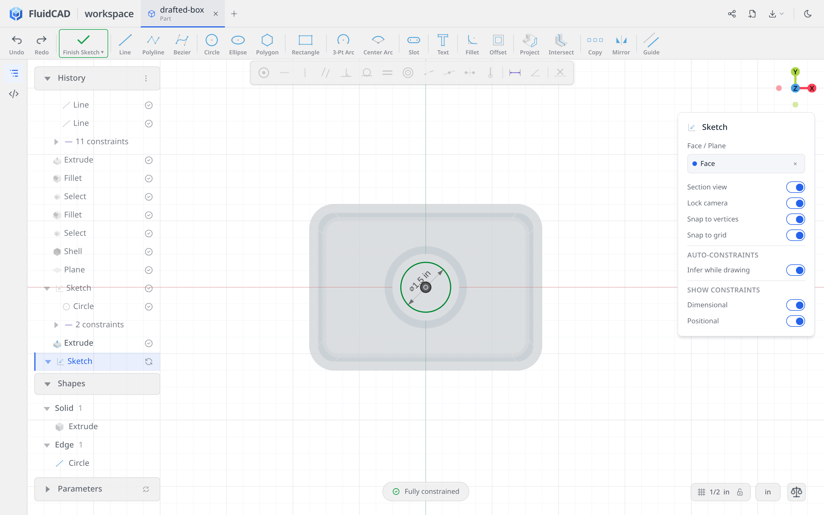
Click Sketch and select the pipe's flat top face. Use Circle again: click the origin, enter diameter 1.5, and press Enter, then Escape.
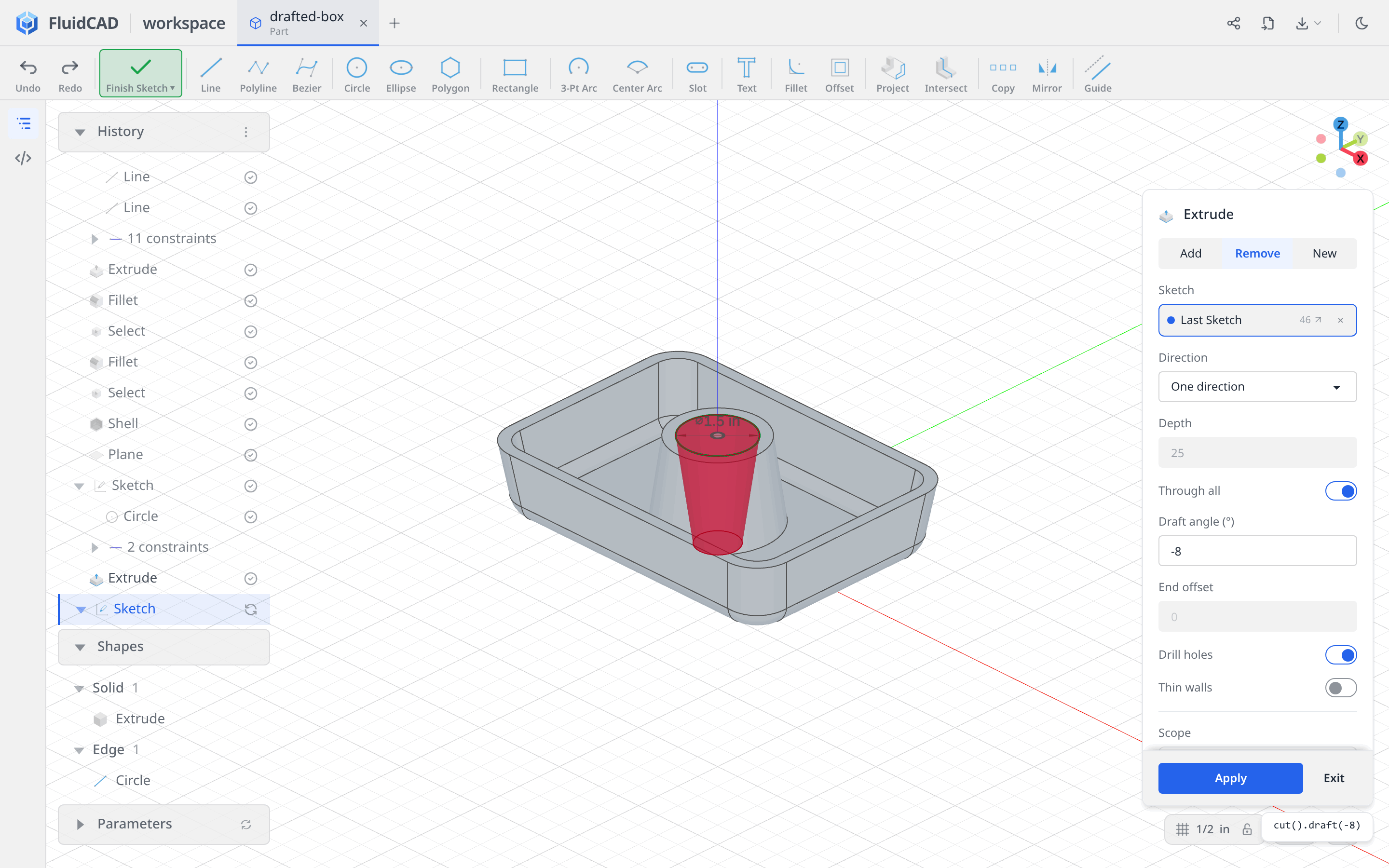
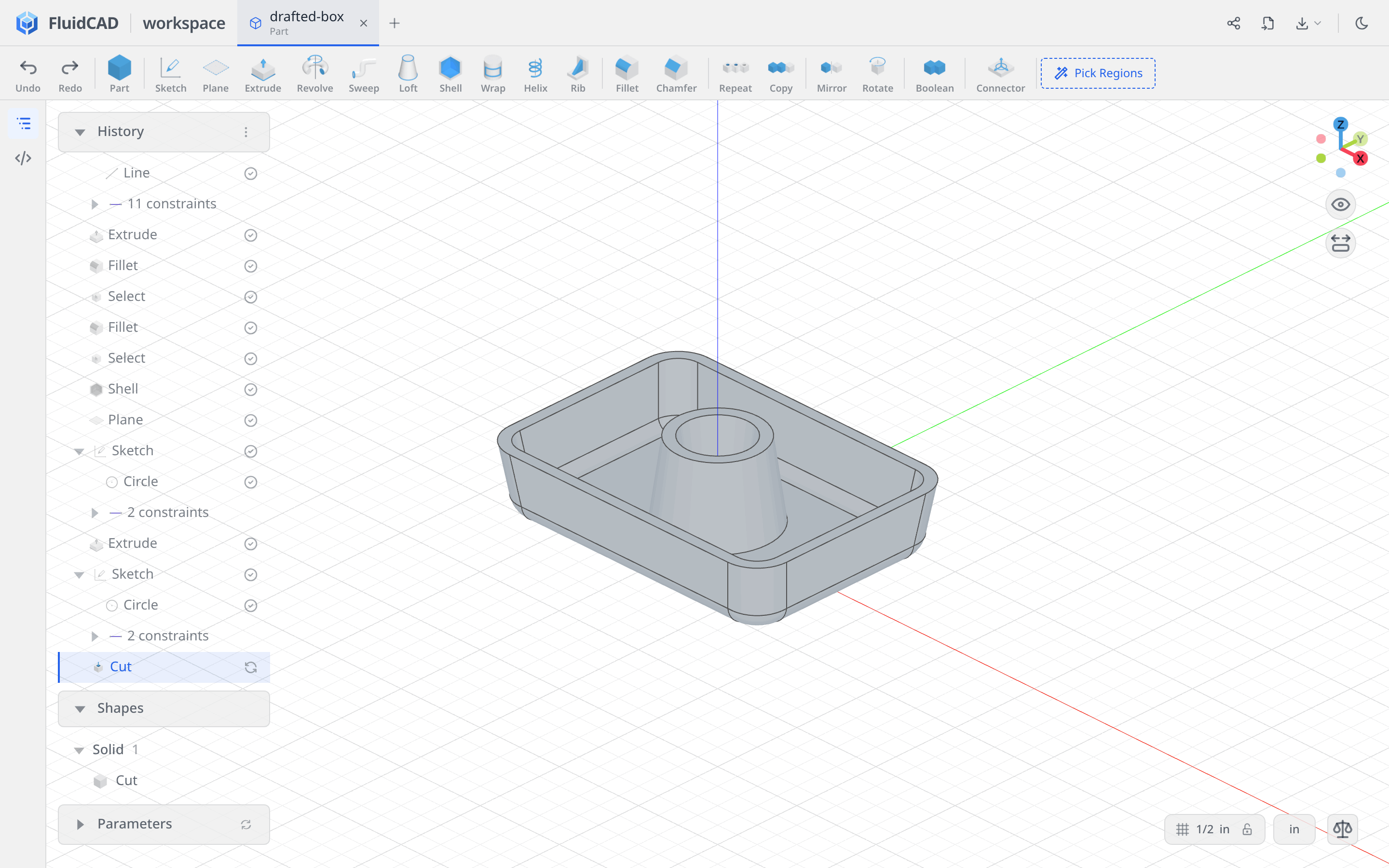
Click Extrude on the toolbar and select Remove. Keep One direction, enable Through all, and set Draft angle (°) to -8. The statement reads cut().draft(-8).
Inspect the red preview: the bore runs down through the pipe and the box floor, narrowing toward the underside. The outside of the pipe flares outward as it descends, so the pipe wall becomes thicker toward the bottom; the two surfaces are not parallel.
Click Apply.
Step 5: Build one support rib
Draw a short spine on XZ
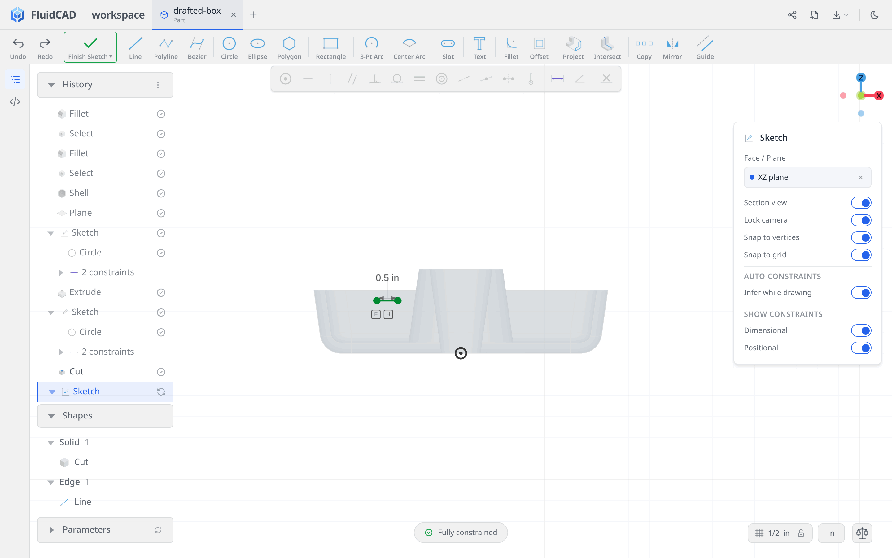
Click Sketch and choose the XZ datum plane. Keep Section view on so you can see through the box.
Choose Line. Use the start point's X / Y coordinate pill to enter -2 and 1.25, using Tab between fields, and confirm the point. In this sketch, Y is the height above the box underside. Move horizontally to the right and type 0.5 for the line's length, then Enter. Its end is at [-1.5, 1.25].
Press Escape, select the line's left endpoint, and click Fix in the constraint bar. The typed length, inferred Horizontal relation, and fixed start make the spine fully constrained. If Horizontal was not inferred, select the line and add it from the constraint bar.
Extend the rib to the surrounding walls
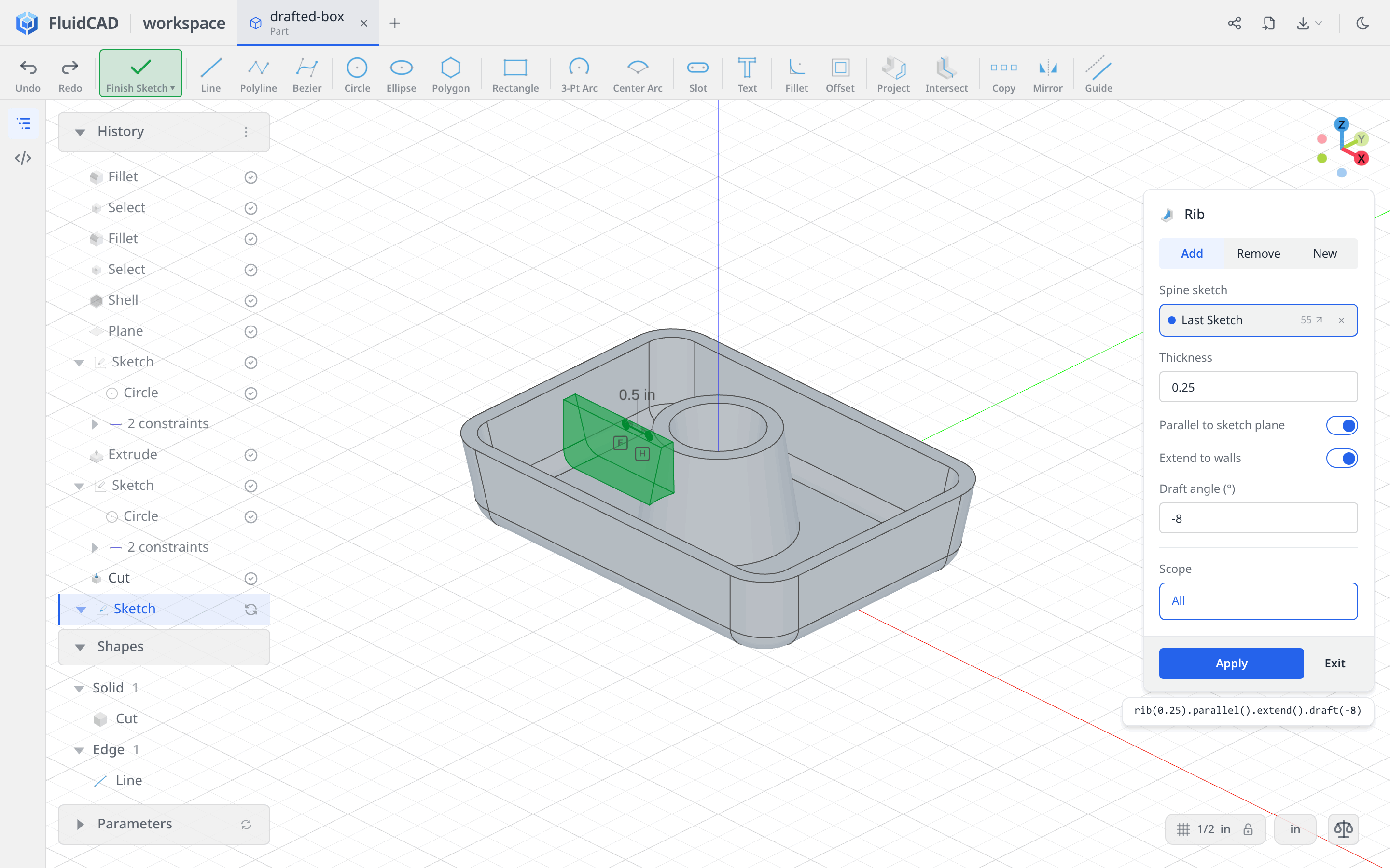
Click Rib on the toolbar. Leave Add selected and set:
- Thickness:
0.25 - Parallel to sketch plane: on
- Extend to walls: on
- Draft angle (°):
-8
The short spine defines the rib's top. Parallel to sketch plane builds the upright wall down toward the floor; Extend to walls bridges the remaining gap from the pipe to the box wall. The statement reads rib(0.25).parallel().extend().draft(-8).
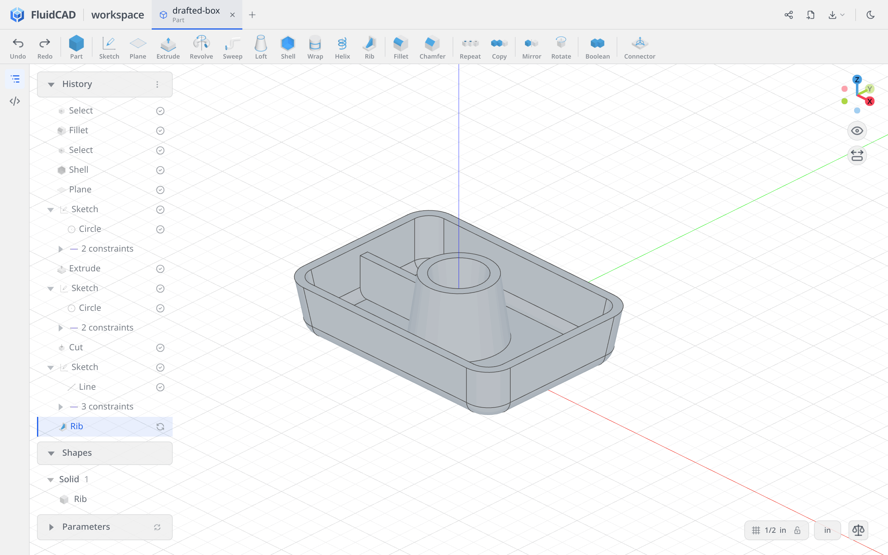
Click Apply.
Step 6: Repeat the rib around Z
Click Repeat and set Type to Circular. Click the Rib row in History to add it to Features. Leave Axis on World Z axis, set Total Count to 4, and Angle (°) to Total 360.
The count includes the original, so the preview adds three ribs at 90° intervals. Repeat rebuilds the rib against the surrounding walls at each position; the shorter sides of the rectangular box get shorter ribs.
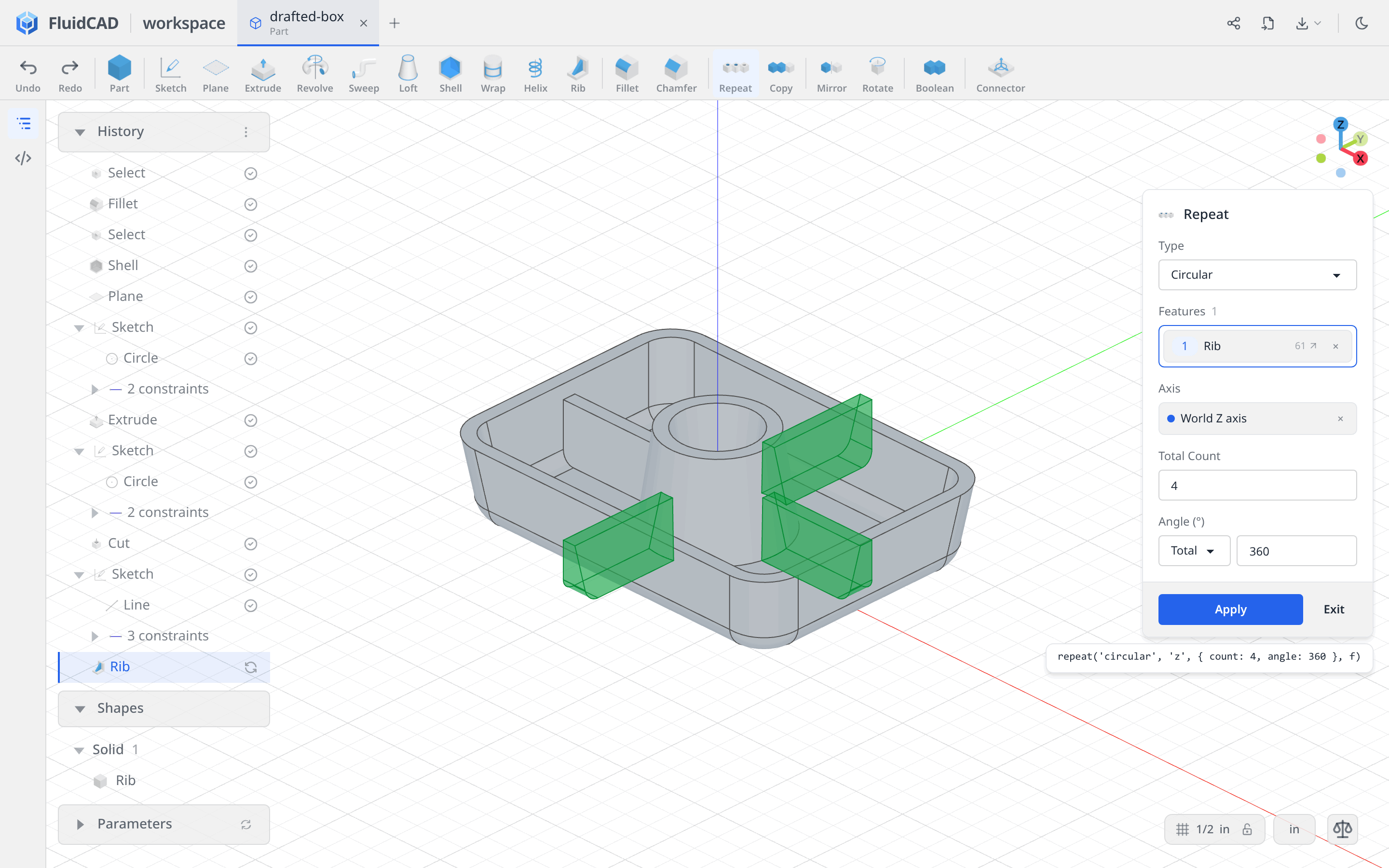
Click Apply.
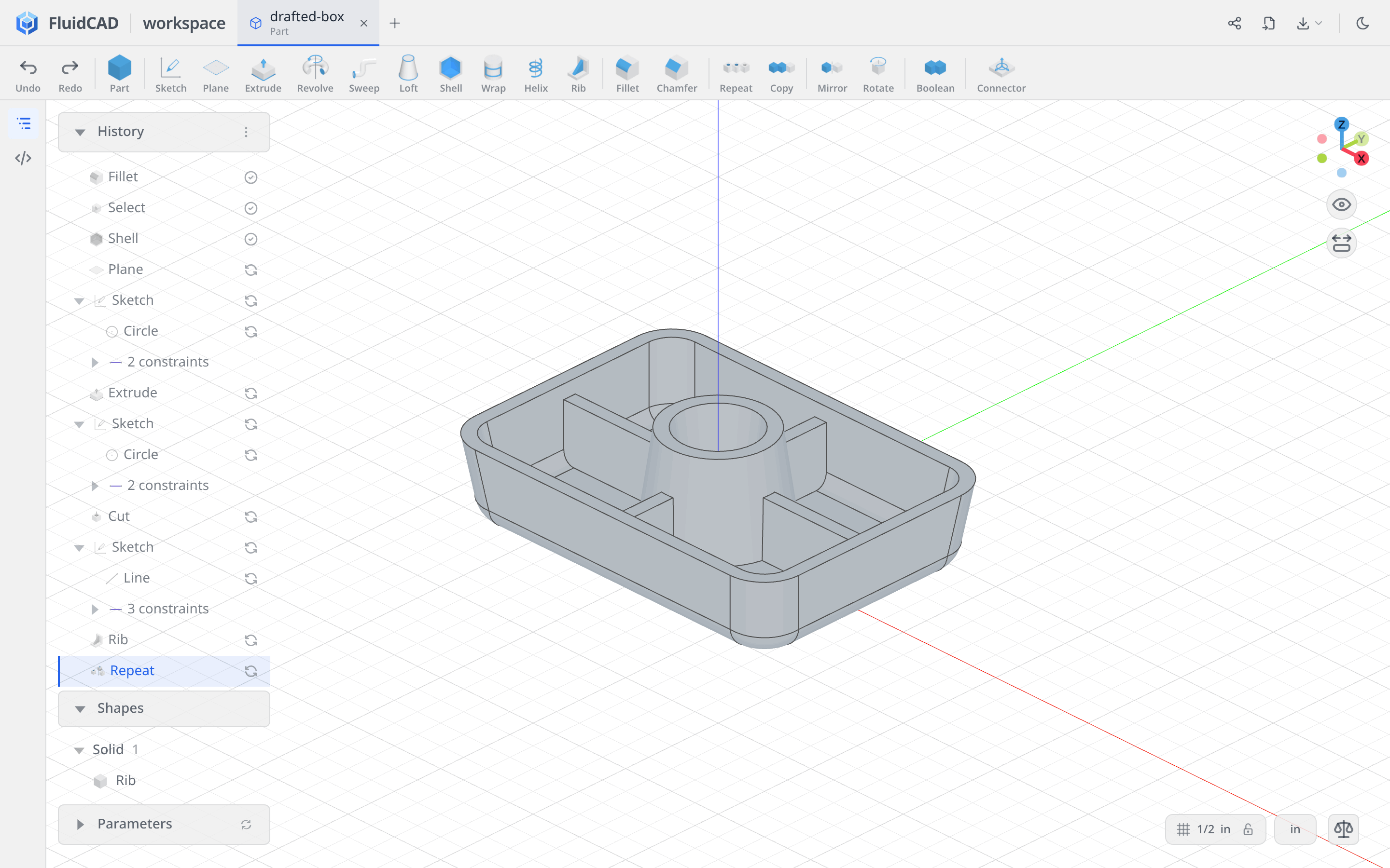
Full code
The tools write the model into drafted-box.fluid.js. Open the code editor with </> on the left rail or Ctrl+B to inspect it. This listing uses descriptive names and keeps the inch unit explicit.
Show the full code
import { circle, cut, extrude, fillet, line, origin, plane, repeat, rib, select, shell, sketch, unit } from 'fluidcad/core';
import { coincident, diameter, distance, fix, horizontal, midpoint, vertical } from 'fluidcad/constraints';
import { edge, face } from 'fluidcad/filters';

unit('in');

// Centered Rectangle: W 7, H 5, on the rim plane.
const rimPlane = plane('xy', 1.5);
sketch(rimPlane, () => {
  const l1 = line([-3.5, -2.5], [3.5, -2.5]);
  const l2 = line([3.5, -2.5], [3.5, 2.5]);
  const l3 = line([3.5, 2.5], [-3.5, 2.5]);
  const l4 = line([-3.5, 2.5], [-3.5, -2.5]);
  coincident(l1.end(), l2.start());
  coincident(l2.end(), l3.start());
  coincident(l3.end(), l4.start());
  coincident(l4.end(), l1.start());
  horizontal(l1);
  horizontal(l3);
  vertical(l2);
  vertical(l4);
  distance(l1.start(), l1.end(), 7);
  distance(l2.start(), l2.end(), 5);
  midpoint(origin(), l1.start(), l3.start());
});

const base = extrude(-1.5).draft(-8);

fillet(0.75, base.sideEdges());
fillet(0.5, select(edge().parallelTo('xz').onPlane('xy').nearest('y').withTangents()));

// Remove the upper face; the rounded lower rim stays in place.
shell(-0.25, select(face().onPlane(base.startFaces())));

const pipePlane = plane('xy', 2);
sketch(pipePlane, () => {
  const pipeCircle = circle([0, 0], 2);
  coincident(pipeCircle.center(), origin());
  diameter(pipeCircle, 2);
});

const pipeBody = extrude(-2).draft(8);

sketch(pipeBody.startFaces(), () => {
  const boreCircle = circle([0, 0], 1.5);
  coincident(boreCircle.center(), origin());
  diameter(boreCircle, 1.5);
});

cut().draft(-8);

// A short horizontal spine; Extend to walls bridges the rest of the gap.
sketch('xz', () => {
  const spine = line([-2, 1.25], [-1.5, 1.25]);
  horizontal(spine);
  fix(spine.start(), [-2, 1.25]);
  distance(spine.start(), spine.end(), 0.5);
});

const support = rib(0.25).parallel().extend().draft(-8);

repeat('circular', 'z', { count: 4, angle: 360 }, support);
What you practiced
- Inches — declare the file's unit before entering dimensions.
- Plane and Rectangle → Centered — place and fully constrain the footprint at the rim height.
- Extrude / Remove → Draft angle — taper the box, pipe, and through bore.
- Fillet and Tangent Edges — round the corners and collect the underside rim.
- Shell — remove the top face and hollow inward.
- Rib → Parallel to sketch plane + Extend to walls — grow a drafted support from a short constrained spine.
- Repeat → Circular — rebuild that rib at four positions around World Z.