Building a Flange With Notch
In this tutorial, you'll build a flange with a notch, based on the original design by Too Tall Toby. You build it entirely from the FluidCAD workspace: the toolbar, the sketch tools, the constraint bar and the feature dialogs. Every dialog writes a line of code into your file as you apply it, so the full code at the end is what the UI produced, not something you type.
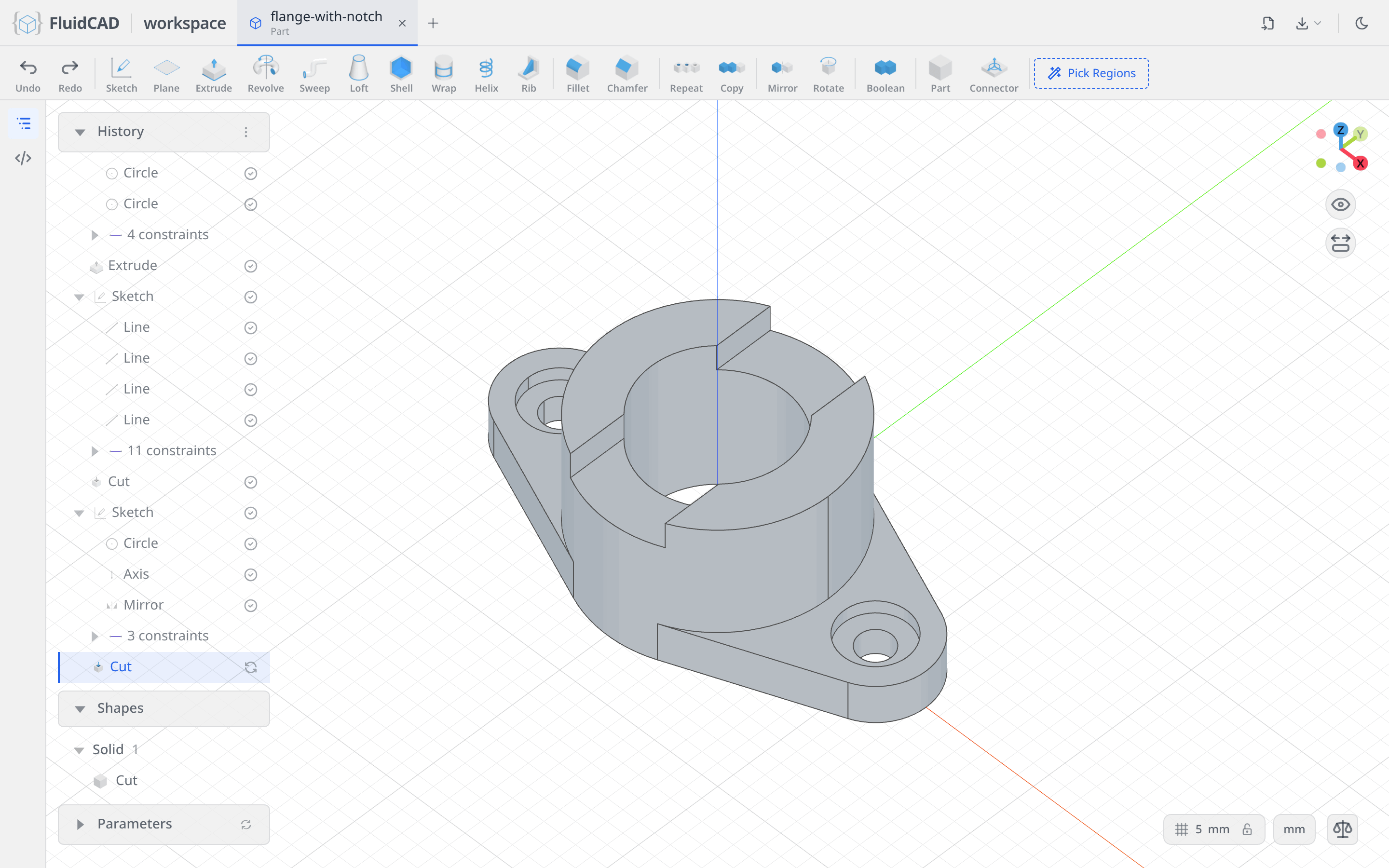
It covers a tangent outline built from a rough sketch and a handful of constraints (Tangent, Concentric, Symmetric and a typed radius), the 2D Mirror tool, sketching on faces the model already has, the centered Rectangle tool, and shallow cuts for a notch and two counterbores.
The drawing gives everything you need: a Ø70 flange with a Ø42 bore, two Ø10 holes 100 apart with R16 tabs around them, a pipe 46 tall, a 30-wide notch 8 deep, and Ø20 counterbores 4 deep.
Before you start
Open a workspace and create a new part file: click + in the top bar and type flange-with-notch.fluid.js. The new tab opens on an empty scene. The screenshots use the light theme; the sun/moon button at the top right switches it.
A few UI habits you will use throughout:
- Ctrl+click adds an entity to the current selection. A plain click replaces it.
- The constraint bar appears under the toolbar while you sketch. Its buttons are icons; hover one for its name. A button lights up only when the current selection makes sense for it.
- Dimension is one button. What it writes depends on what you picked: a circle gives a diameter, an arc a radius, a point and an axis a distance.
- The DOF pill at the bottom of the viewport counts the degrees of freedom left in a sketch and turns into Fully constrained when you are done. Every sketch in this tutorial ends there.
- Every feature dialog shows the statement it is about to write, just under the dialog. Apply (or Enter) writes it; Exit / Cancel (or Escape) discards it.
- Picking a point that sits under a dimension label picks the label instead. Zoom in with the wheel until the label clears, pick, and zoom back out.
Step 1: The flange profile
Start a sketch on the XY plane
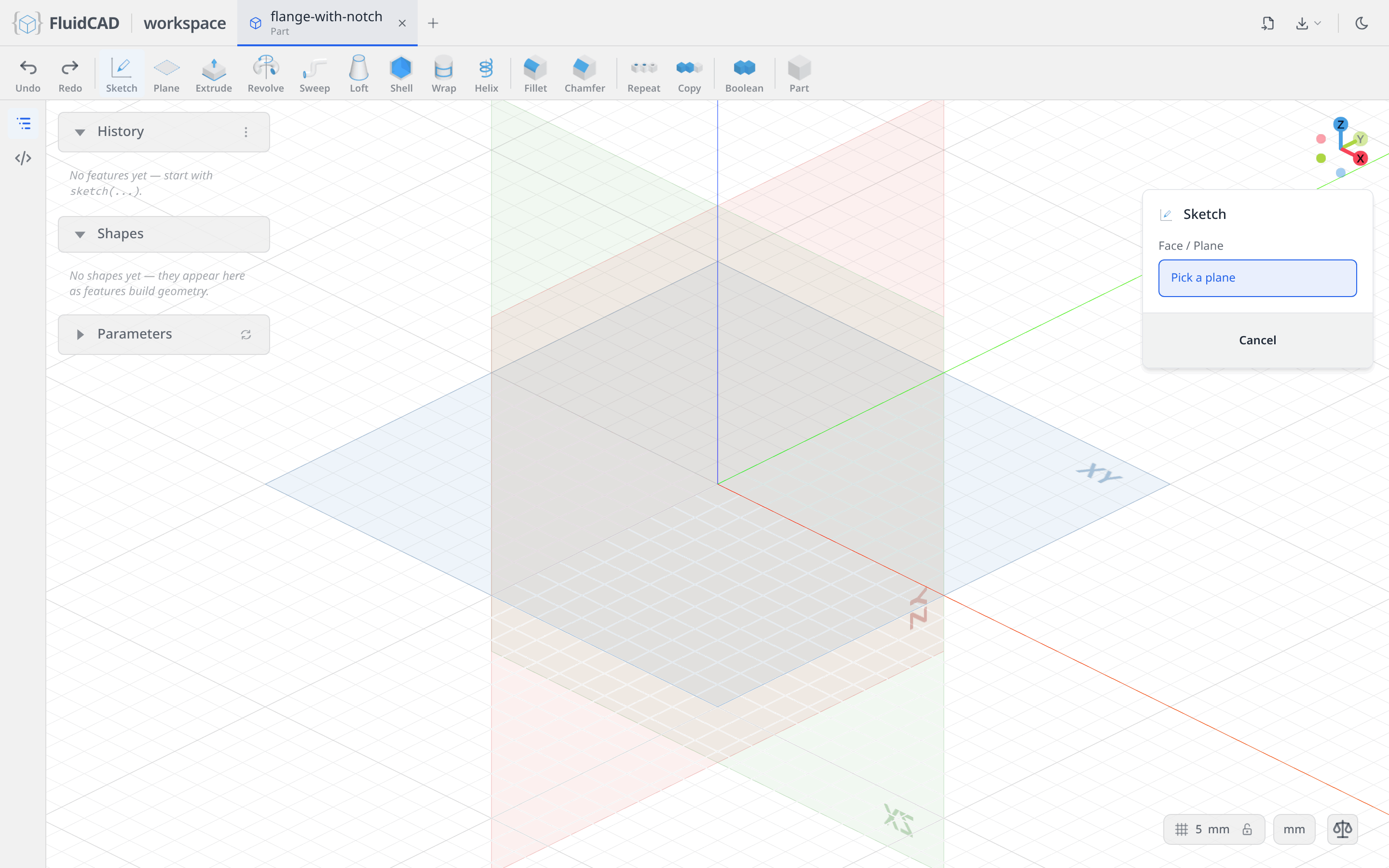
Click Sketch in the toolbar. The dialog asks for a face or a plane, and the three origin planes appear in the viewport.
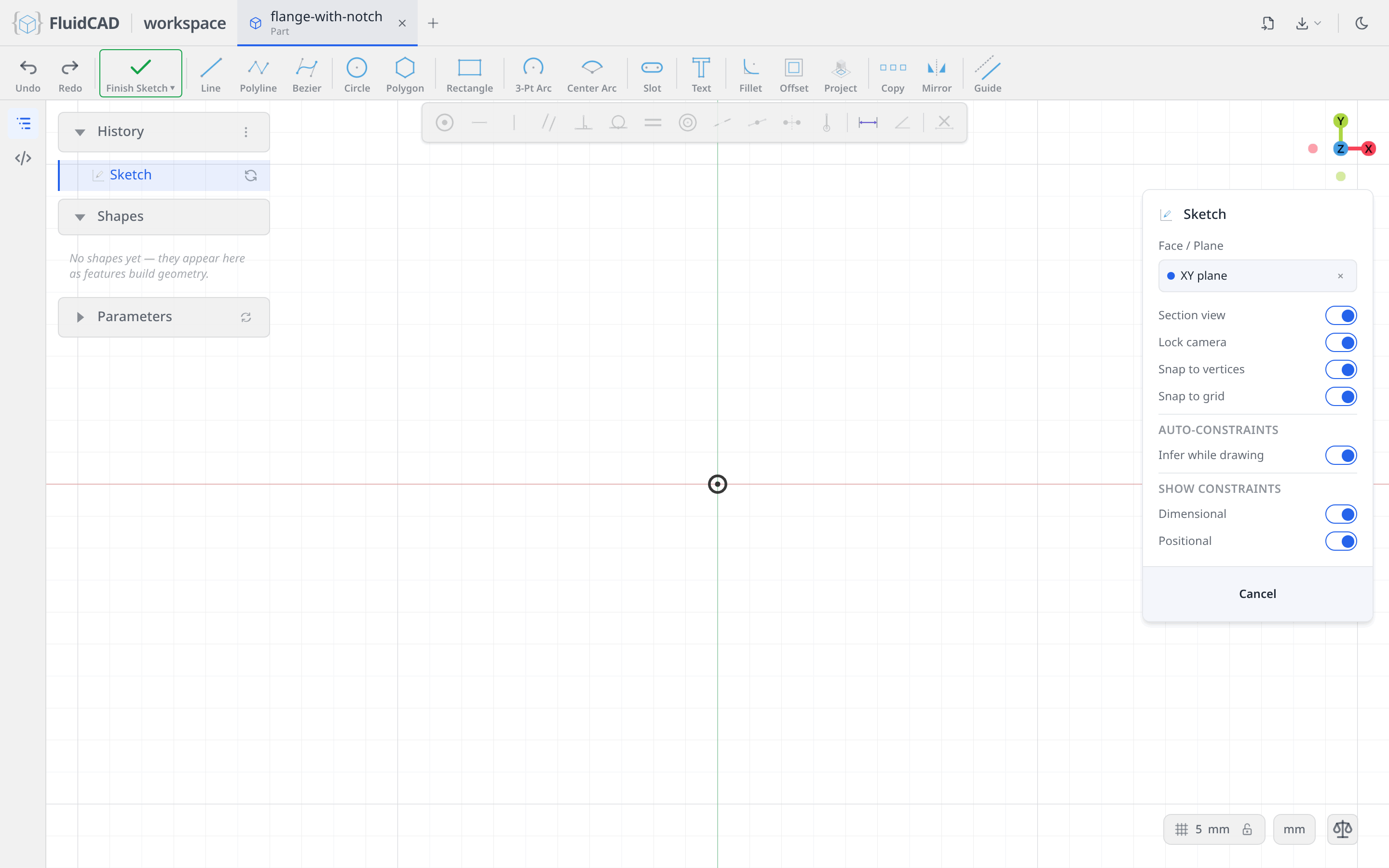
Click the XY plane. The camera locks onto it, the sketch toolbar replaces the feature toolbar, and the constraint bar appears above the viewport.
Three circles
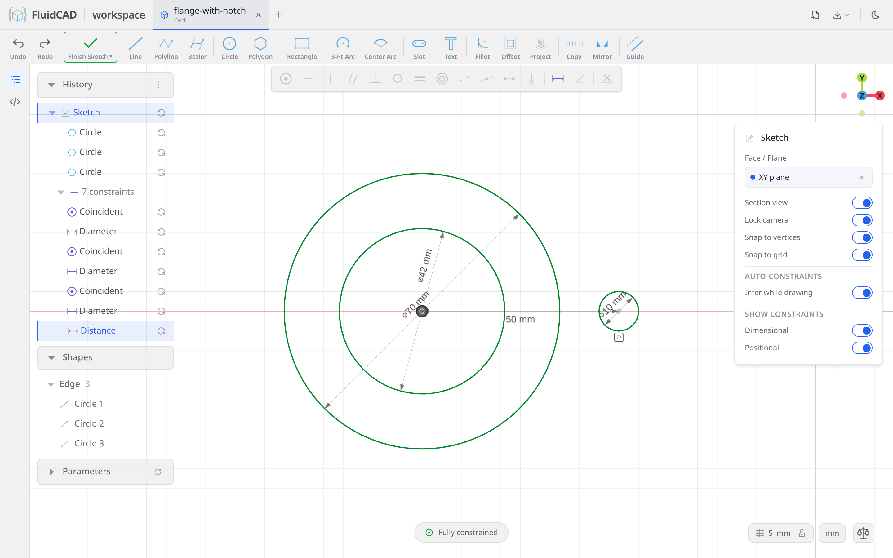
Pick Circle, click the origin, type 70 and press Enter. Clicking the origin snaps the centre to it, so the circle arrives with a coincident to the origin and its diameter: Fully constrained straight away. Do it again for the bore: click the origin, type 42.
Now the bolt hole. Click a point on the horizontal axis to the right of the circles and type 10. Snapping to the axis writes coincident(hole.center(), xAxis()), which leaves one degree of freedom: where along the axis. Click the hole's centre, Ctrl+click the vertical axis, click Dimension and type 50.
Rough out one tab
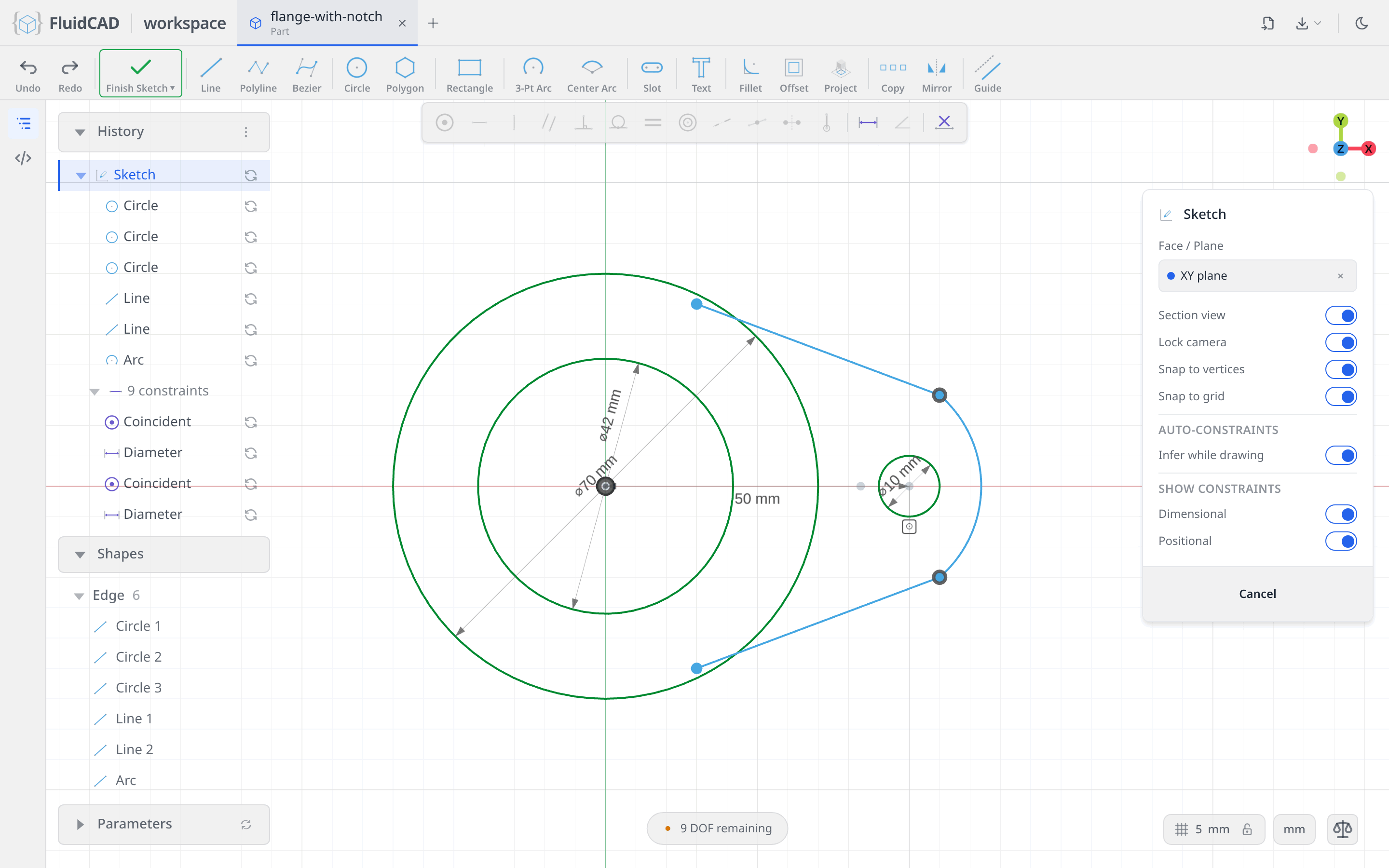
The tab around the hole is two flanks tangent to the outer circle and an R16 cap concentric with the hole. Draw it roughly and let the constraints place it: pick Line and draw a flank from the upper part of the outer circle out to the upper right of the hole. Draw a second Line below the axis, mirrored by eye. Then pick 3-Pt Arc, click the end of the lower line, the end of the upper line, and a third point out past the hole for the bulge. Snapping the arc onto the two line ends writes the two coincidents for free.
Do not try to be accurate. These are guesses; only the shape of the loop matters.
Say what the tab is
Now the constraint bar, one relation at a time. Watch the DOF pill count down.
- Click the upper flank, Ctrl+click the outer circle, click Tangent. The line swings onto the circle.
- Click the upper flank's start point, Ctrl+click the outer circle, click Coincident. The line now starts exactly at the tangency point.
- Click the arc, Ctrl+click the hole (pick the hole on its right side, away from its Ø10 label), click Concentric.
- Click the arc alone, click Dimension, type
16. On an arc, Dimension writes aradius. - Click the upper flank, Ctrl+click the arc, click Tangent.
- Click the upper flank's start point, Ctrl+click the lower flank's start point, Ctrl+click the horizontal axis, click Symmetric.
- Click the lower flank, Ctrl+click the arc, click Tangent.
The pill reads Fully constrained with nothing redundant. No coordinates were typed for the tab at all: the outer circle, the hole and the R16 decide where the flanks touch down.
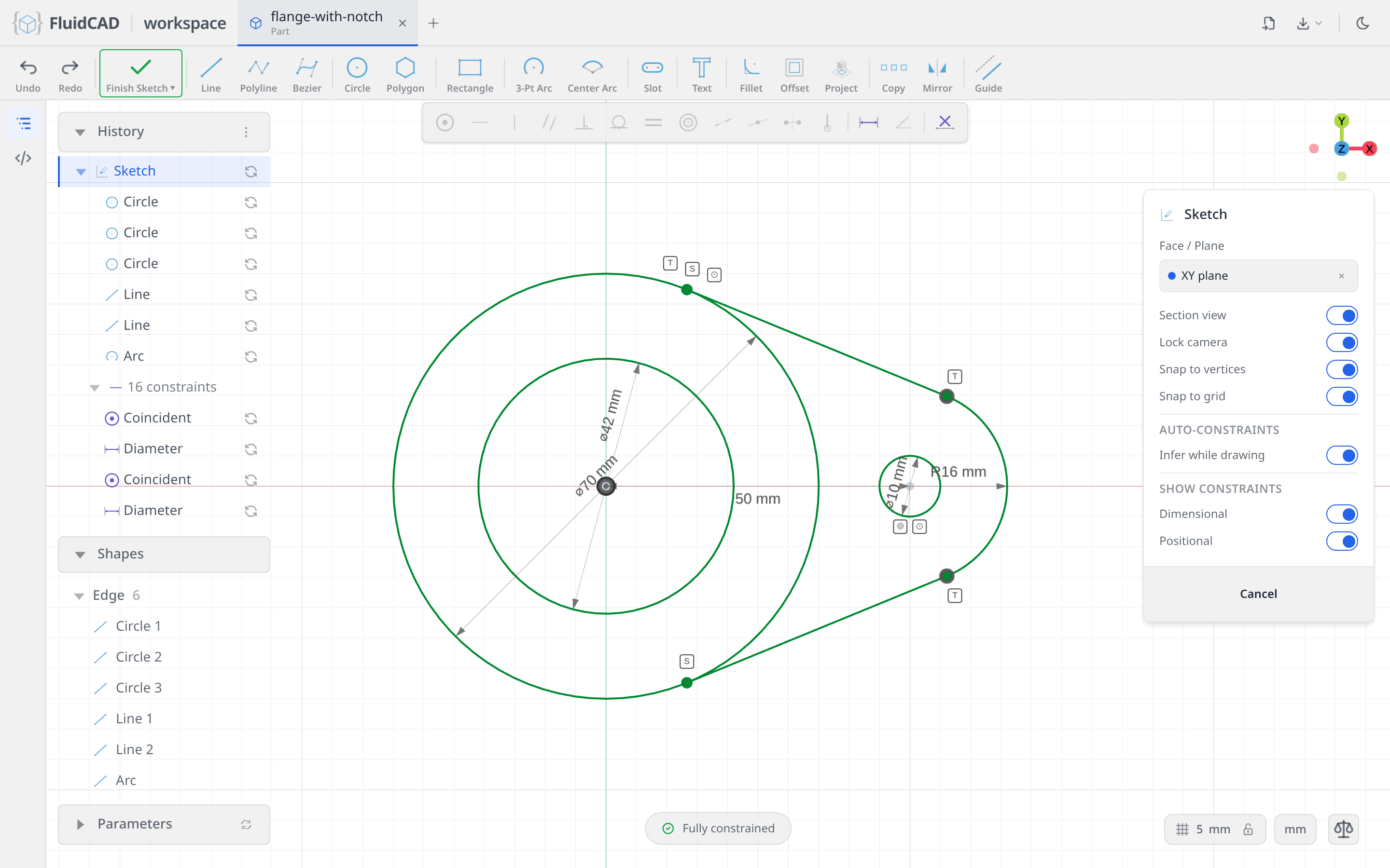
A line tangent to two curves could sit on either side of them. The guess decides: the solver keeps each flank on the side you drew it, so drawing it roughly in the right place is the choice.
Mirror the tab
Pick the Mirror tool from the sketch toolbar. Click the upper flank, the arc, the lower flank and the hole for Geometry, then click the Mirror line slot and click the vertical axis. The blue outline is the mirrored copy and the statement reads mirror(yAxis(), upper, cap, lower, hole).
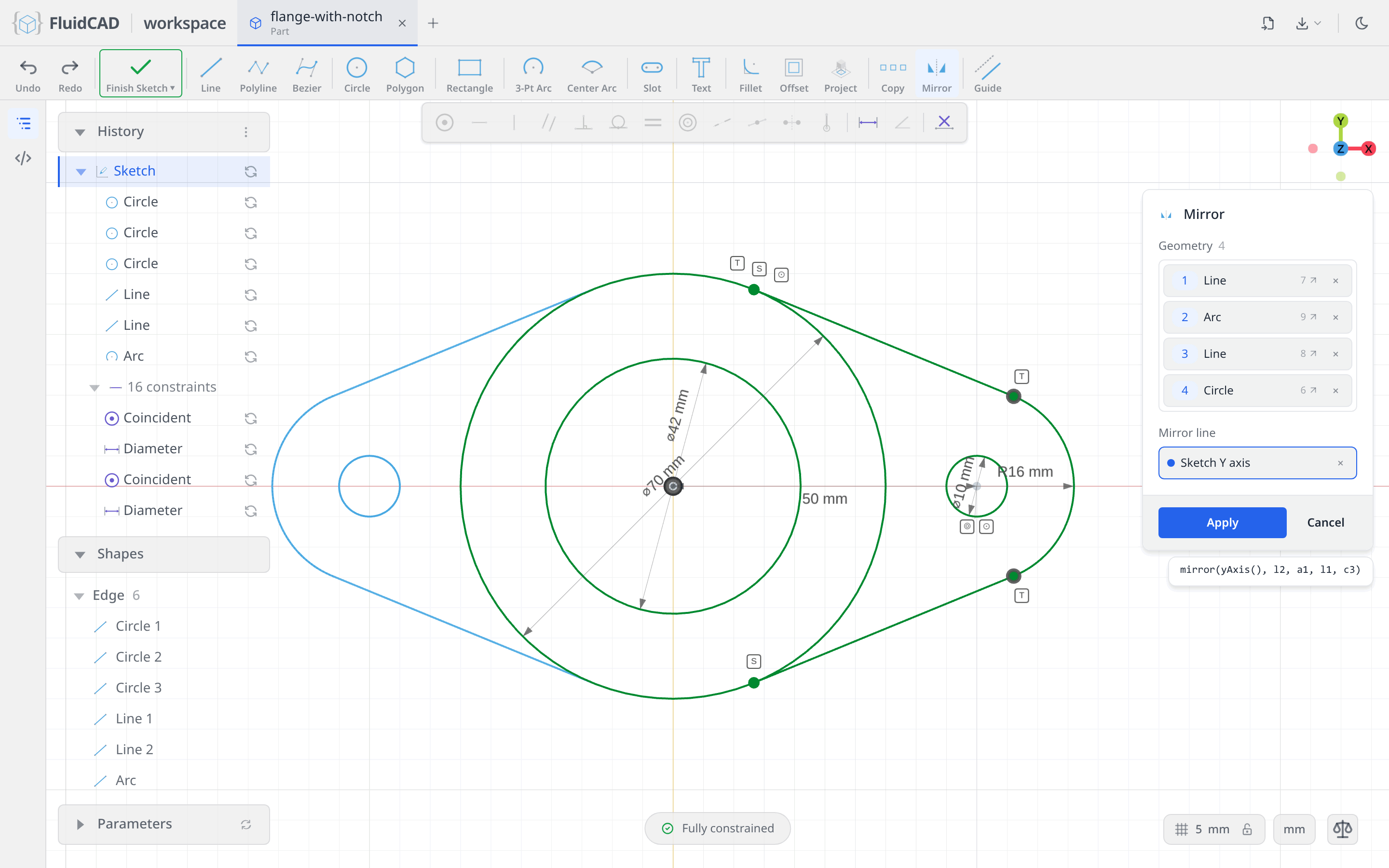
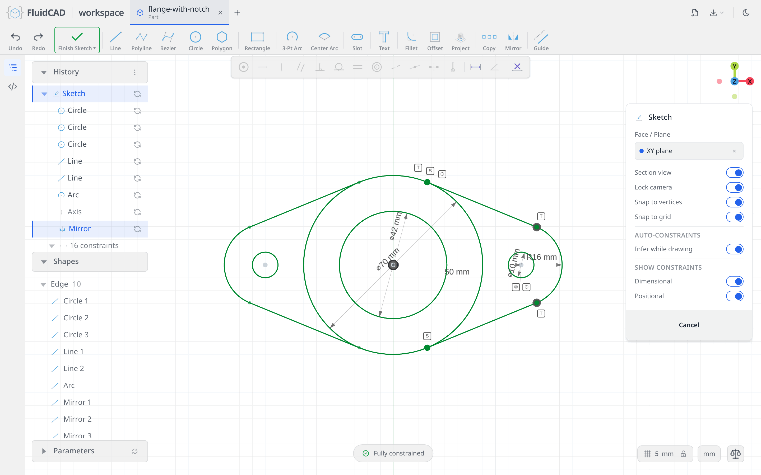
Click Apply. The profile is complete and still fully constrained; the mirrored half follows the original.
Extrude the flange
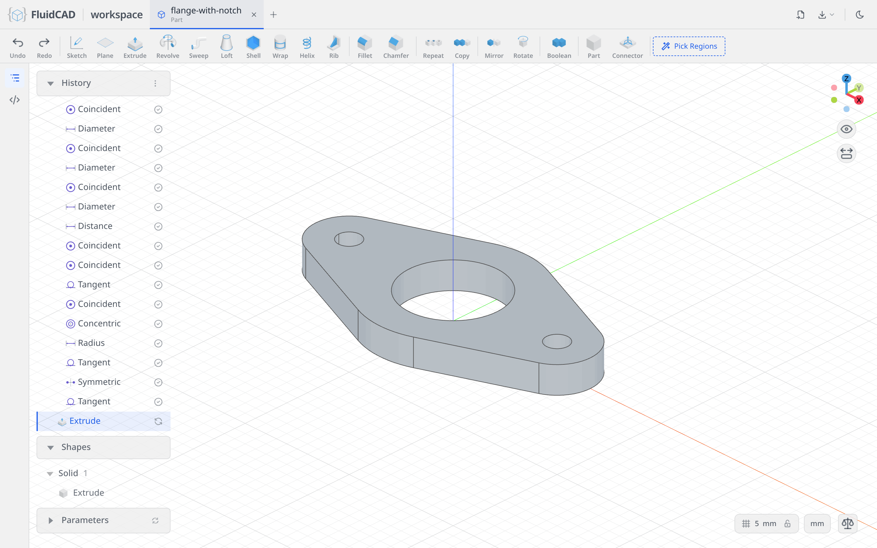
Click Extrude on the toolbar. Set Distance to 12. The green ghost is the live preview, and the statement reads extrude(12). The two inner loops, the bore and the holes, become holes on their own because Drill holes is on.
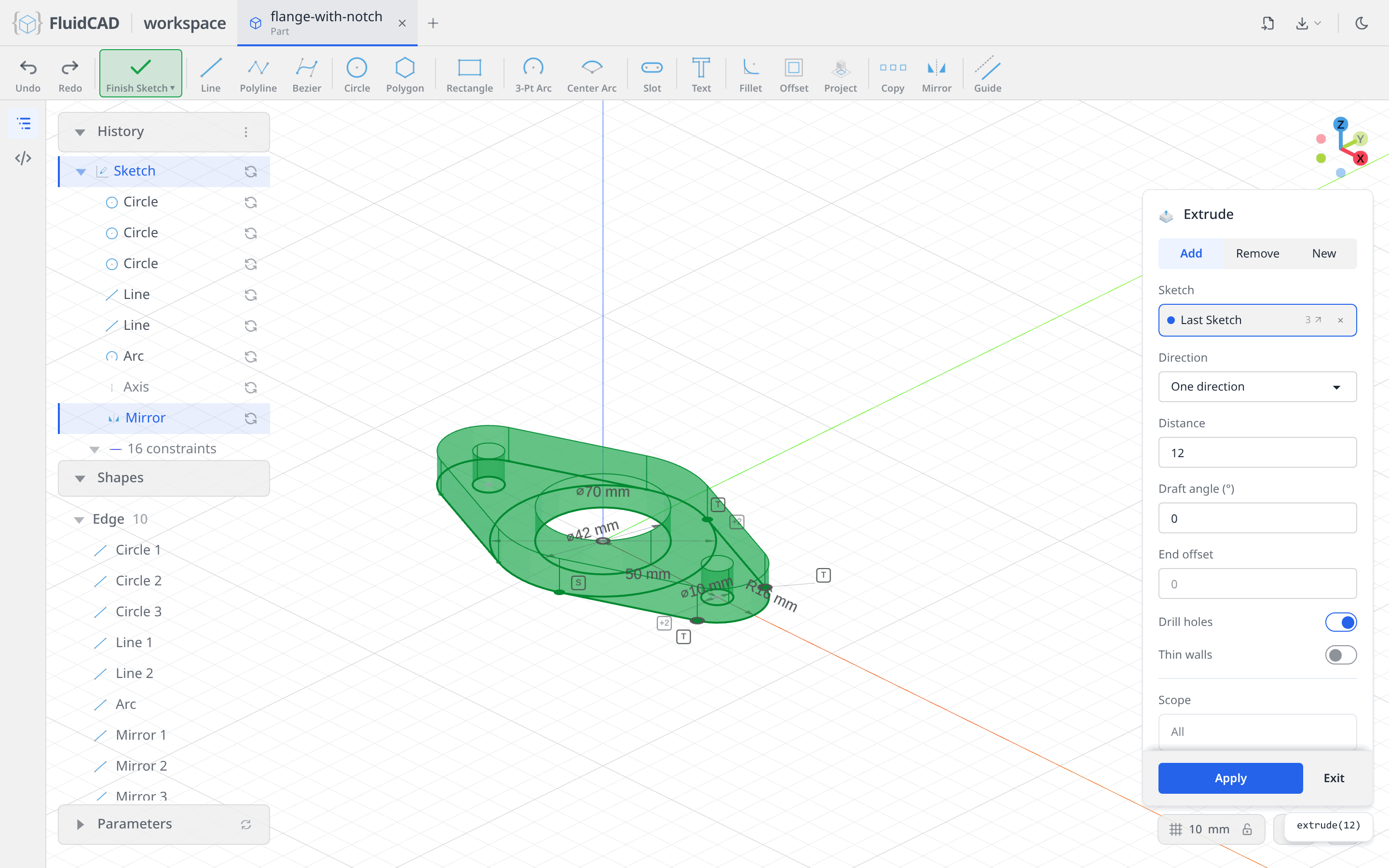
Click Apply.
Step 2: The pipe
Sketch on the flange's top face
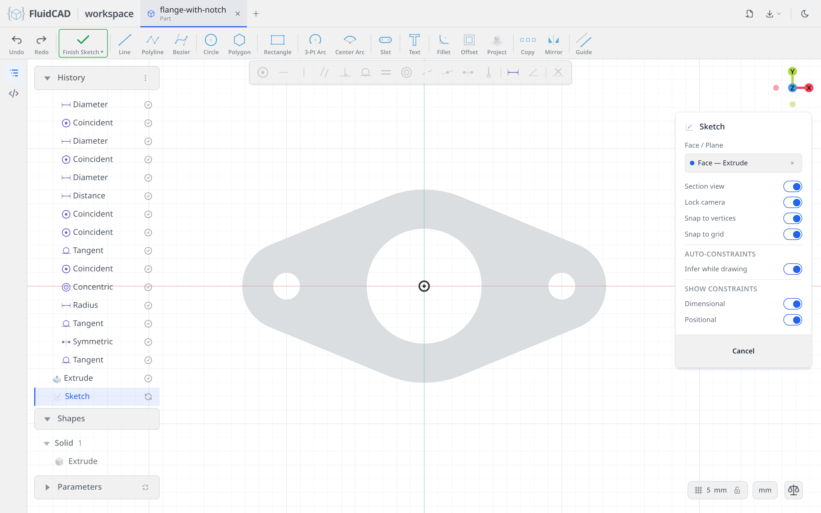
Click Sketch and this time click the top face of the flange. The chip reads Face — Extrude: FluidCAD remembered which operation produced that face, so the sketch follows the flange if you change it later. The section view shows the flange in grey with the origin at the bore's centre.
Two circles on the origin
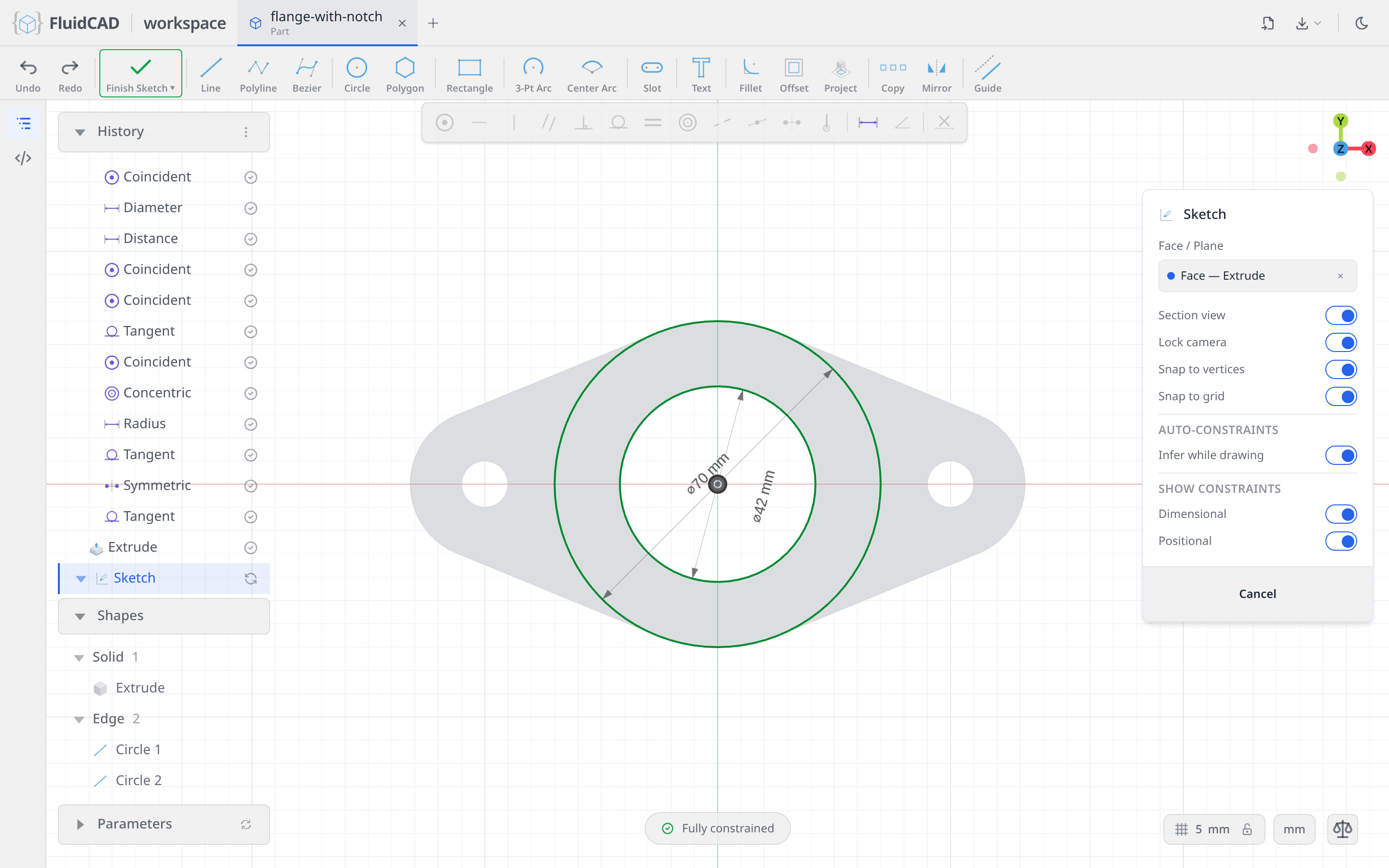
Pick Circle, click the origin, type 70. Click the origin again and type 42. Both snap to the origin, so the ring is fully constrained the moment it is drawn.
Extrude the ring
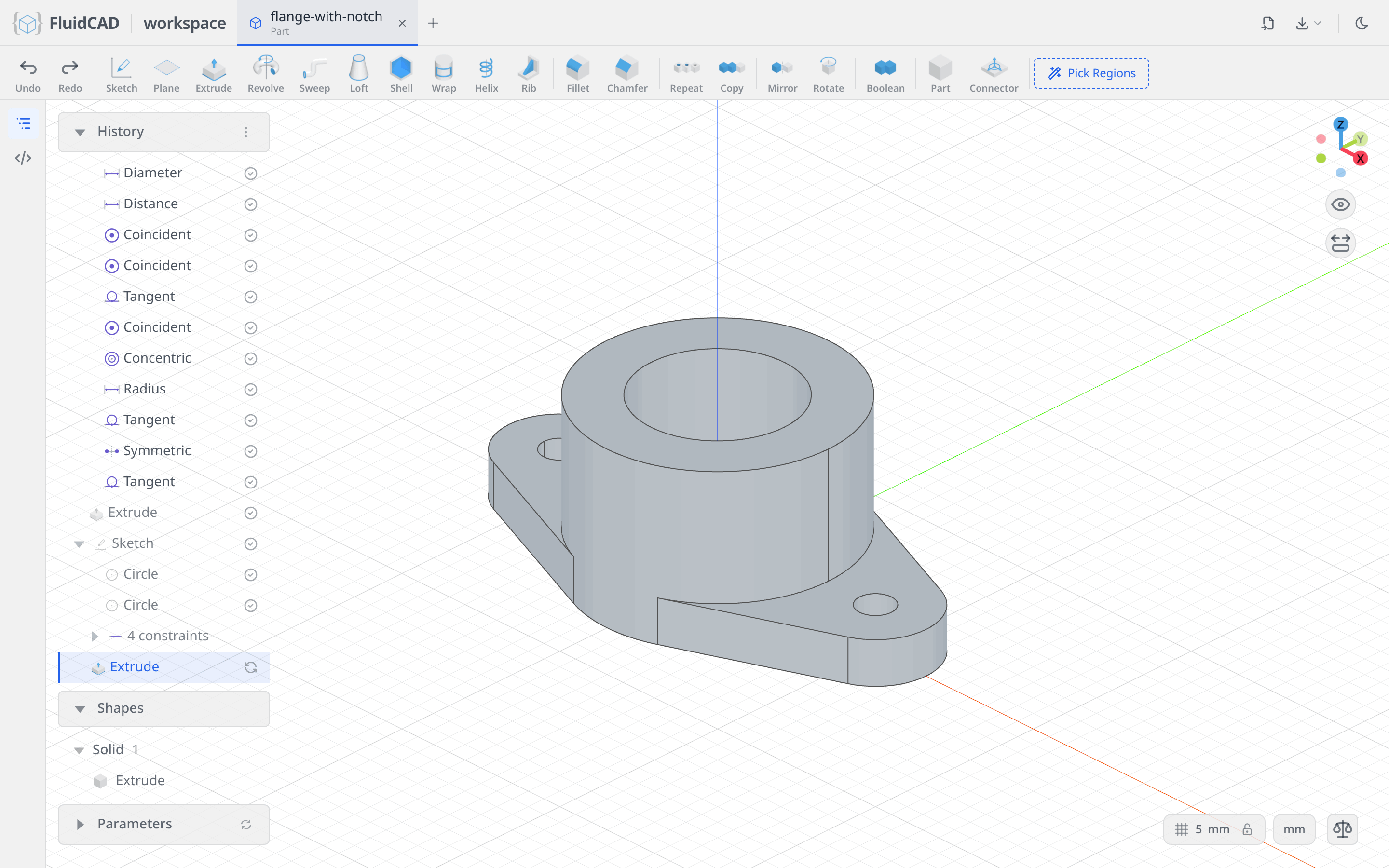
Extrude, Distance 34. The flange is 12 tall and the pipe tops out at 46, so the ring grows by 34 from the face it sits on.
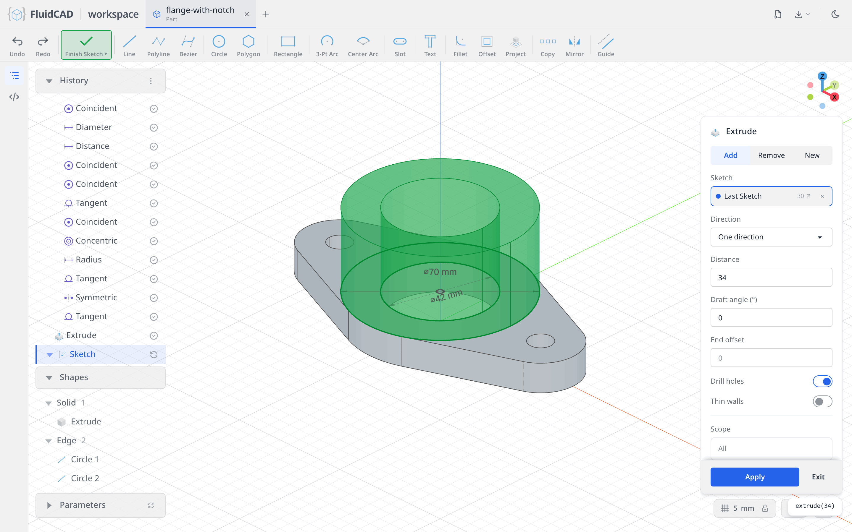
Click Apply. The tube fuses onto the flange, sharing its bore.
Step 3: The notch
Sketch on the pipe's top face
Tilt the view so you look down on the pipe, click Sketch, and click the top rim of the pipe. The datum planes also sit in the pick set, so if the chip says XZ plane rather than Face — Extrude, clear it with ✕ and click the rim from a steeper angle.
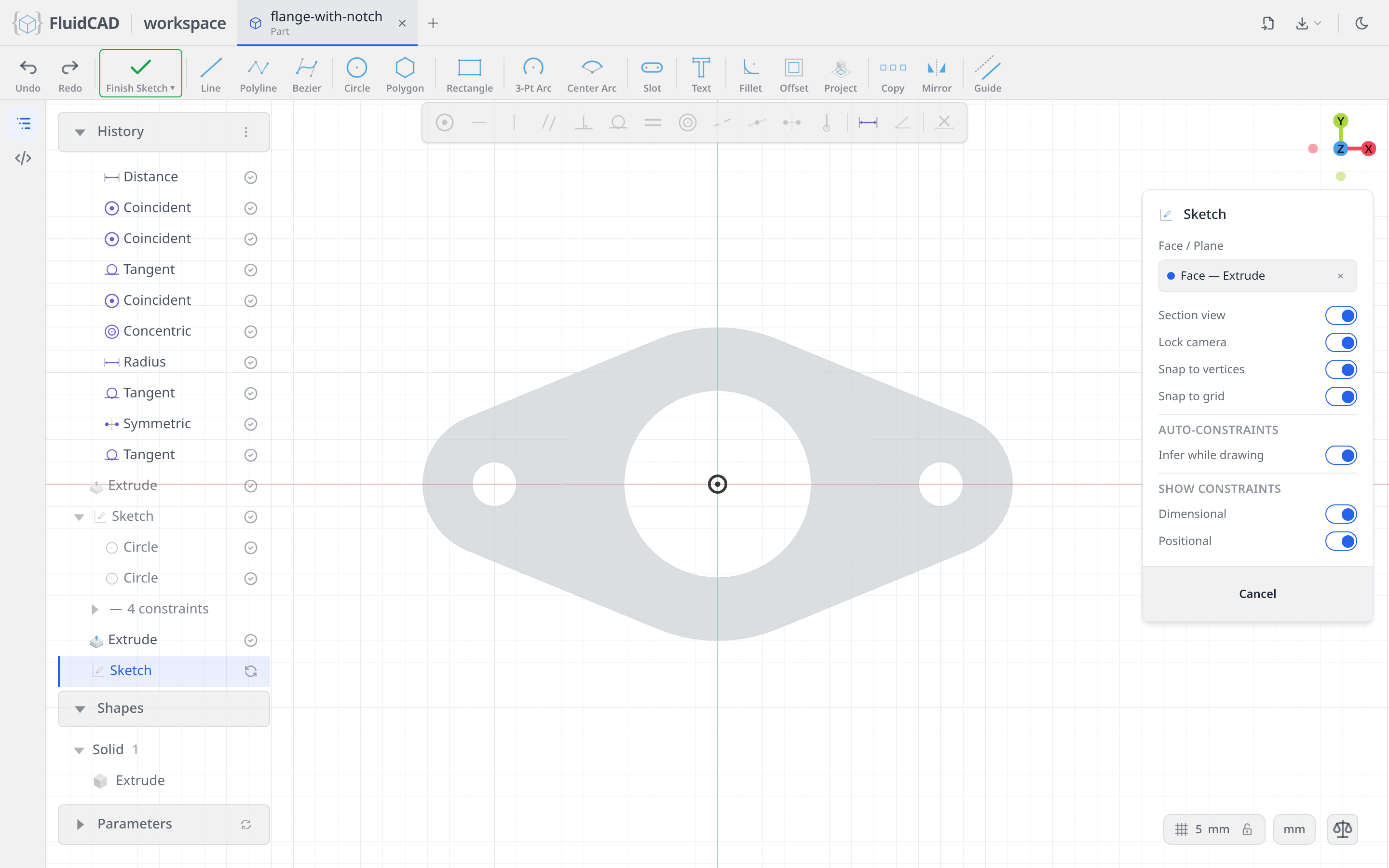
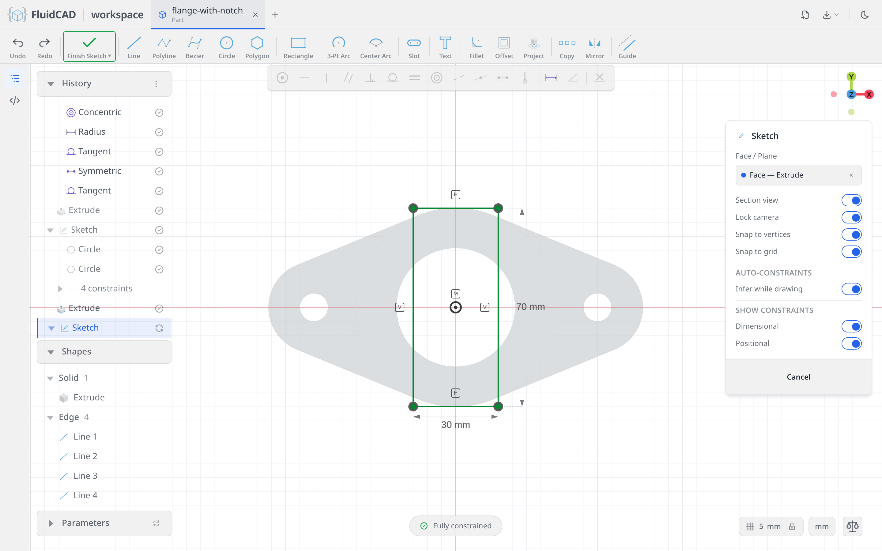
A centered rectangle
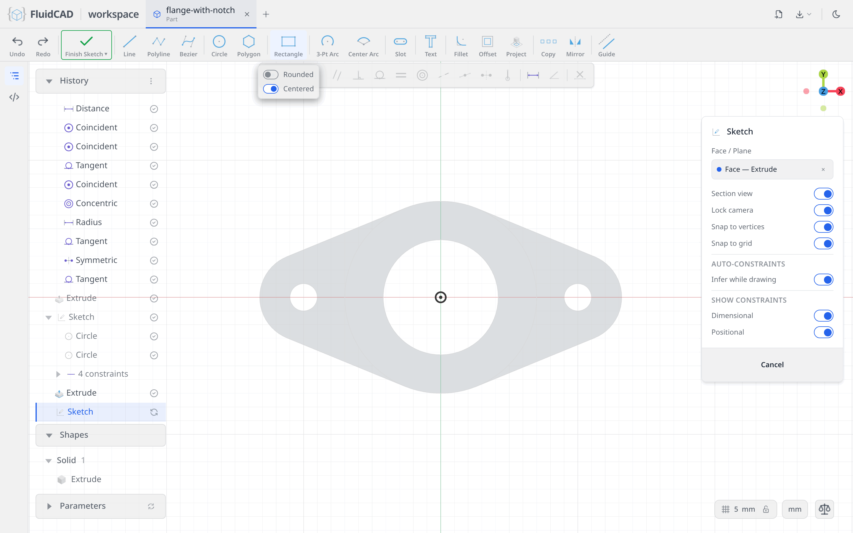
The notch is 30 wide and runs right across the pipe, so it is a 30 × 70 rectangle centered on the origin. Click Rectangle and switch on Centered in its option menu; the rectangle then grows from its middle instead of from a corner.
Click the origin. A W readout follows the mouse; type 30 and press Enter. The readout switches to H; type 70 and press Enter.
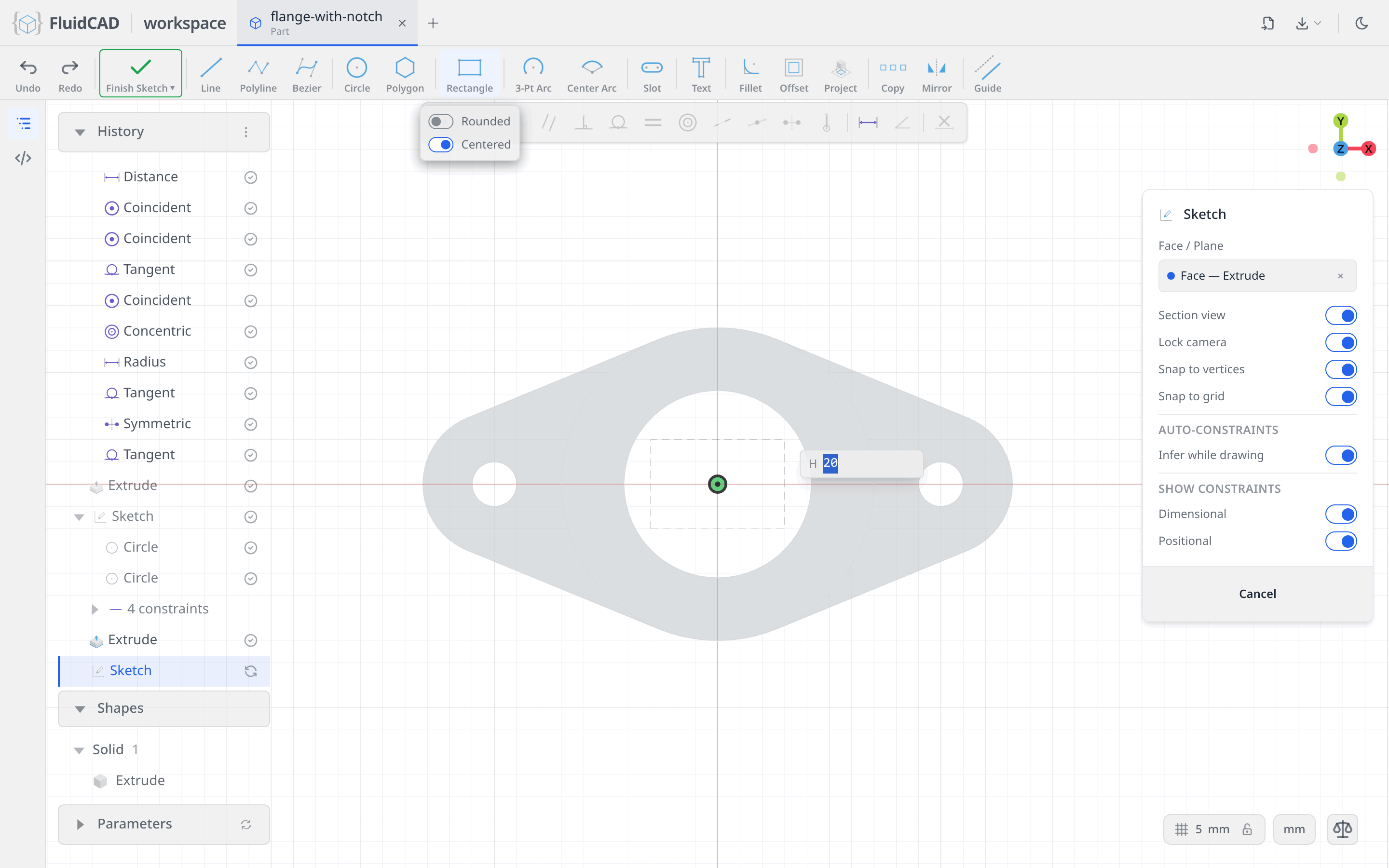
One gesture writes four lines, their corner coincidents, two horizontals, two verticals, the 30 and 70 dimensions, and, because you clicked the origin, a midpoint tying the rectangle's centre to it. Fully constrained.
Cut it 8 deep
Extrude, switch to the Remove tab, Depth 8. The red ghost shows the material about to go; the statement reads cut(8).
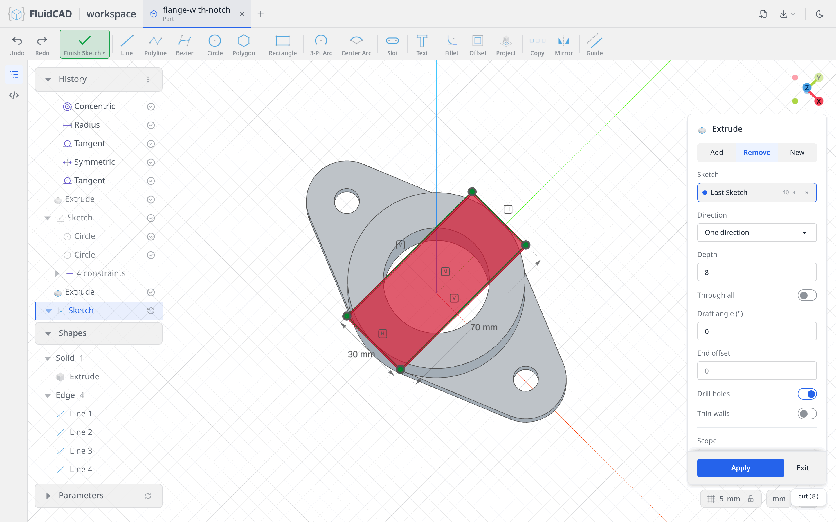
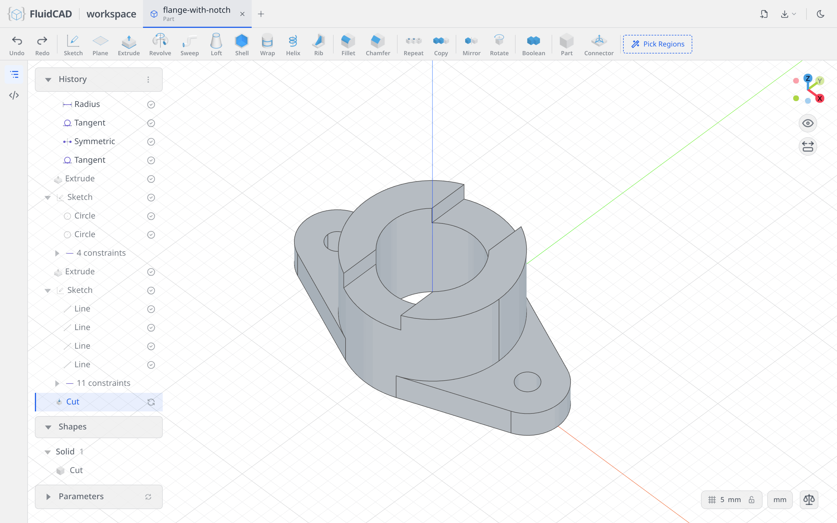
Click Apply. The rectangle only meets solid where it crosses the pipe wall, so one cut makes both sides of the notch.
Step 4: Counterbores
Back to the flange top
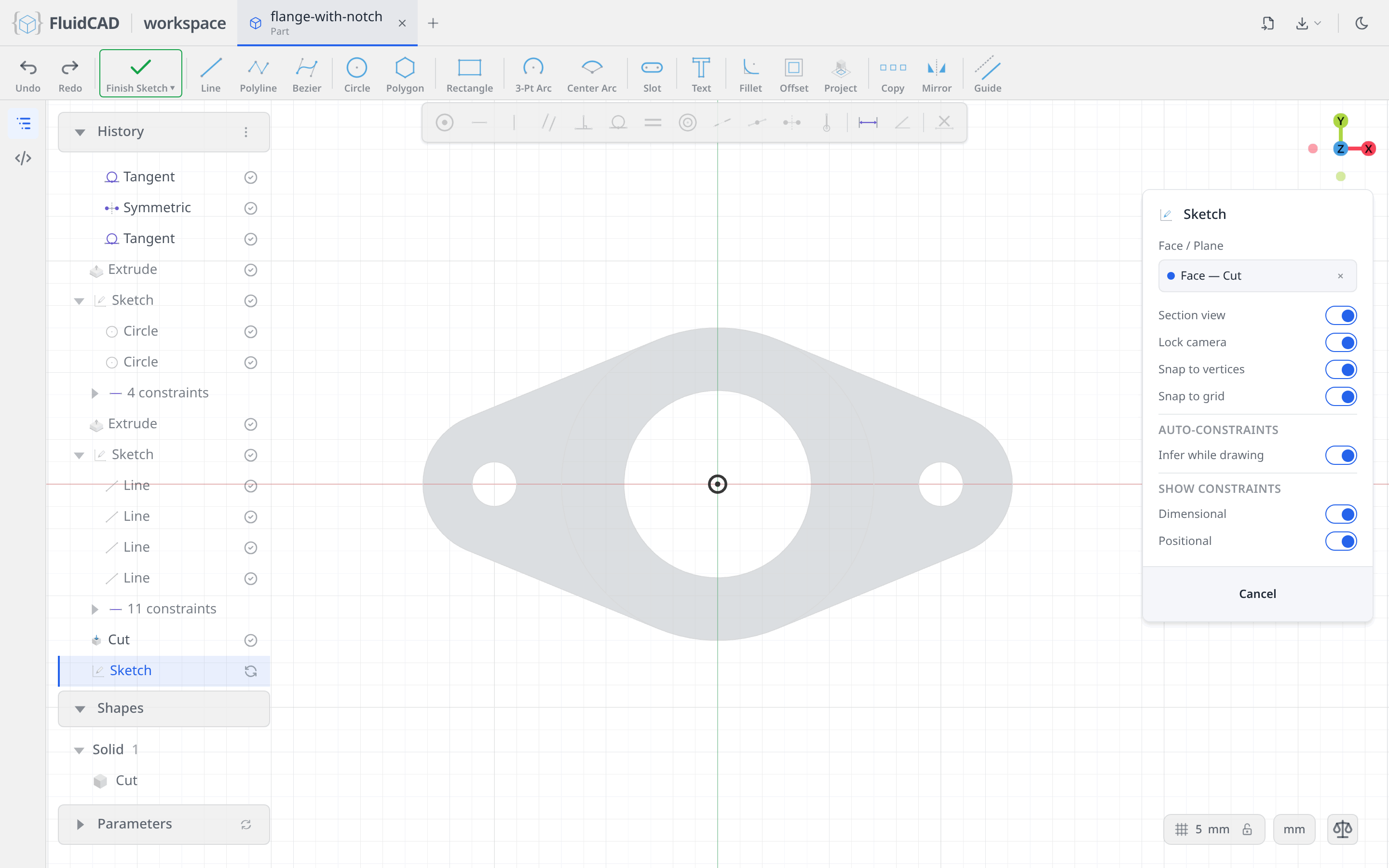
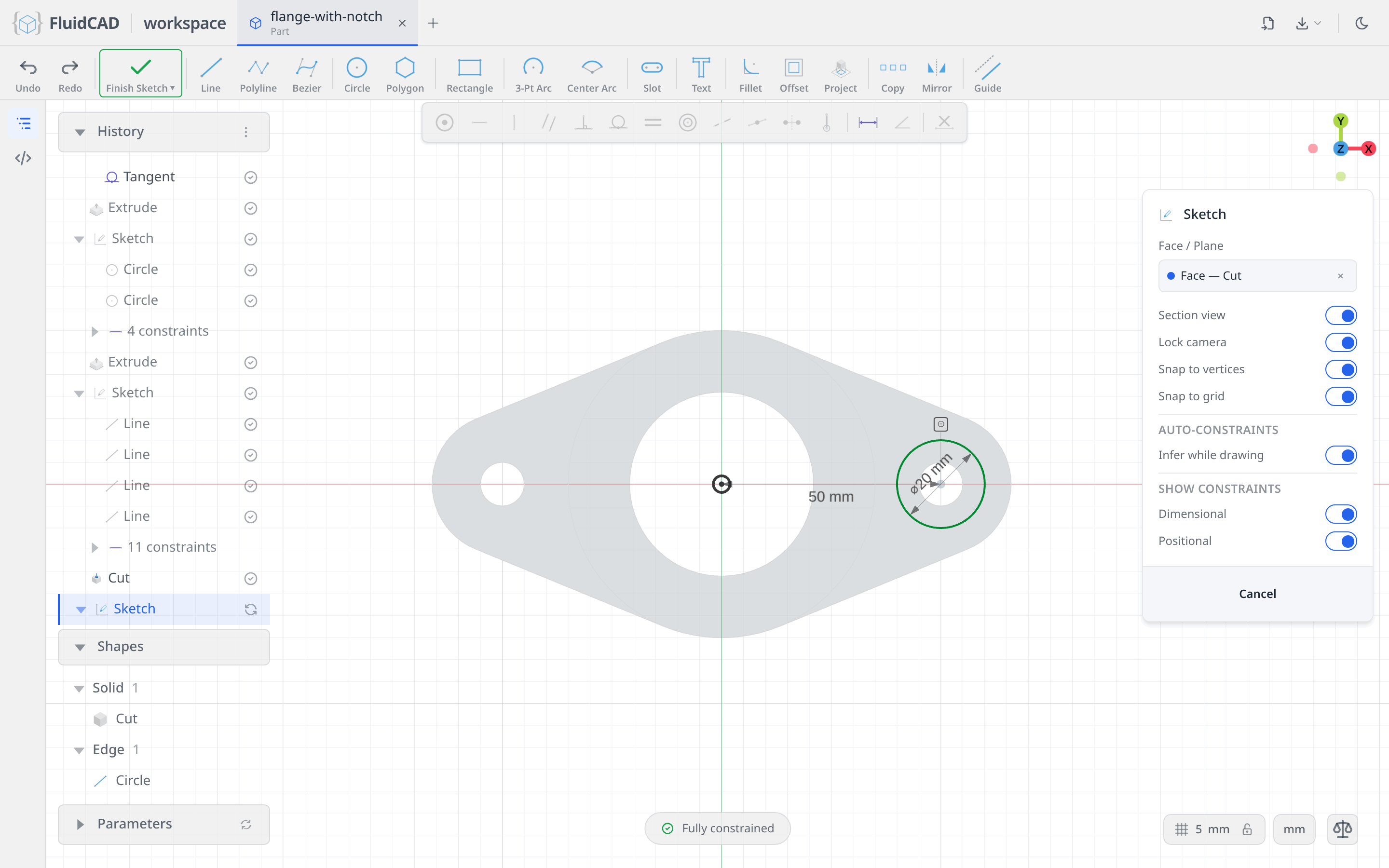
Click Sketch and click the flange's top face again, out on one of the tabs. The chip says Face — Cut now, because the last feature to touch the body was the notch, but the statement still names the flange's own end face.
One Ø20 circle over the hole
Pick Circle, click the centre of the right bolt hole (the snap finds it), type 20. The snap only placed the centre, it did not constrain it, so the pill still counts 2 DOF. Zoom in on the hole so its Ø20 label clears the centre, then click the circle's centre, Ctrl+click the vertical axis, Dimension, 50; and again the centre, Ctrl+click the horizontal axis, Coincident. Fully constrained.
Mirror it
Pick Mirror, click the circle, click the Mirror line slot and click the vertical axis.
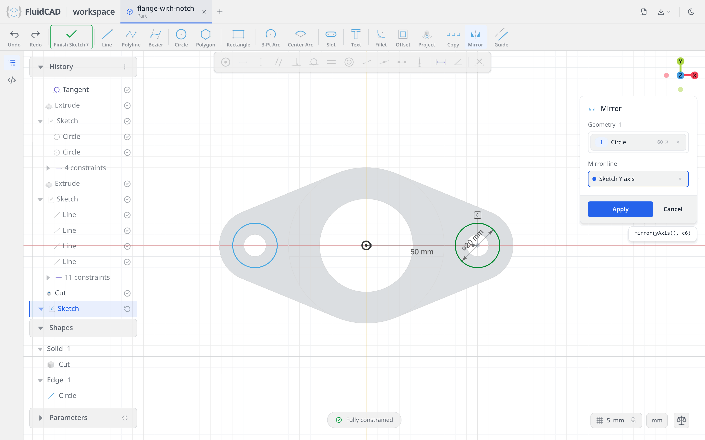
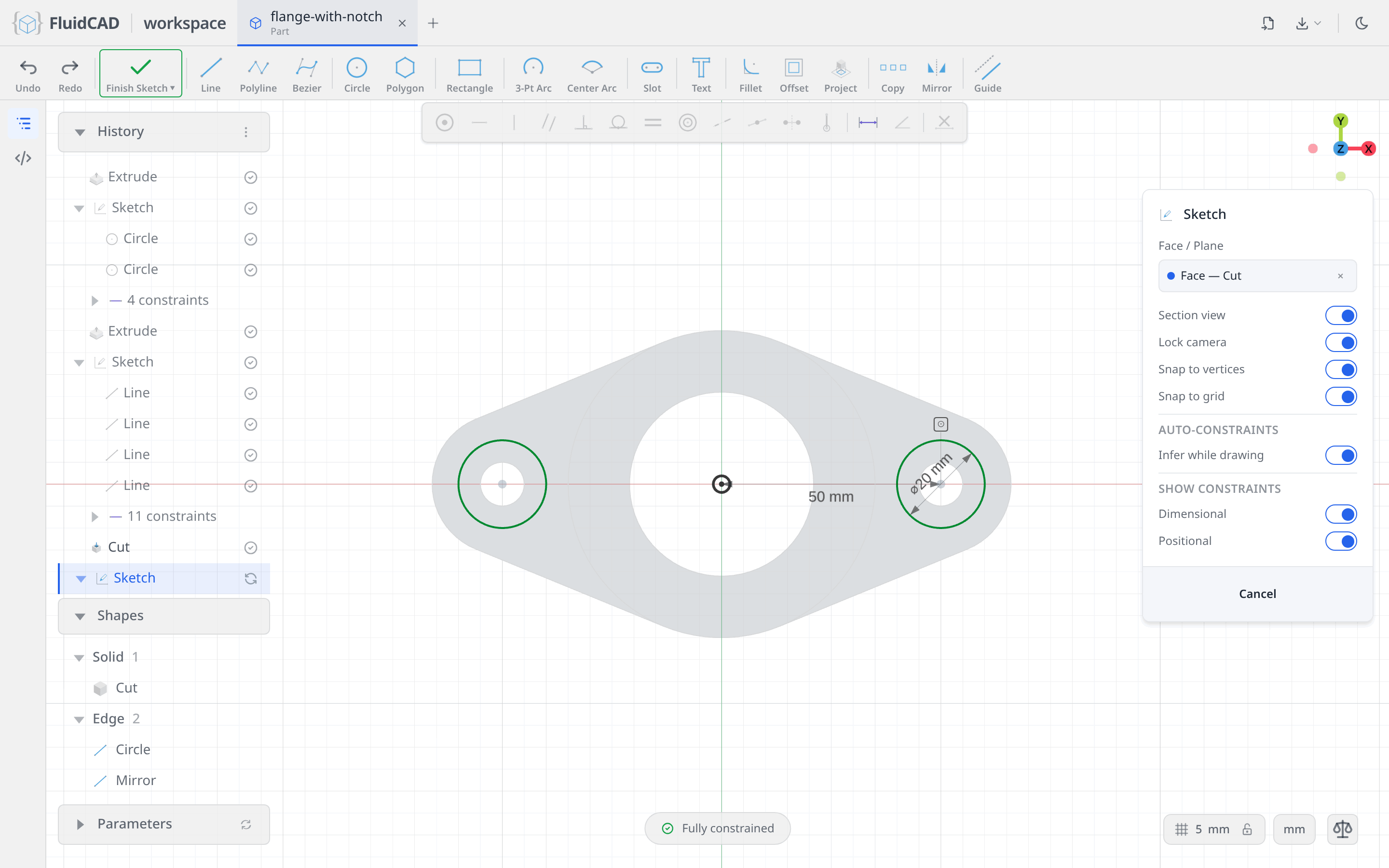
Click Apply. Two counterbores from one constrained circle.
Cut them 4 deep
Extrude, Remove tab, Depth 4. The statement reads cut(4).
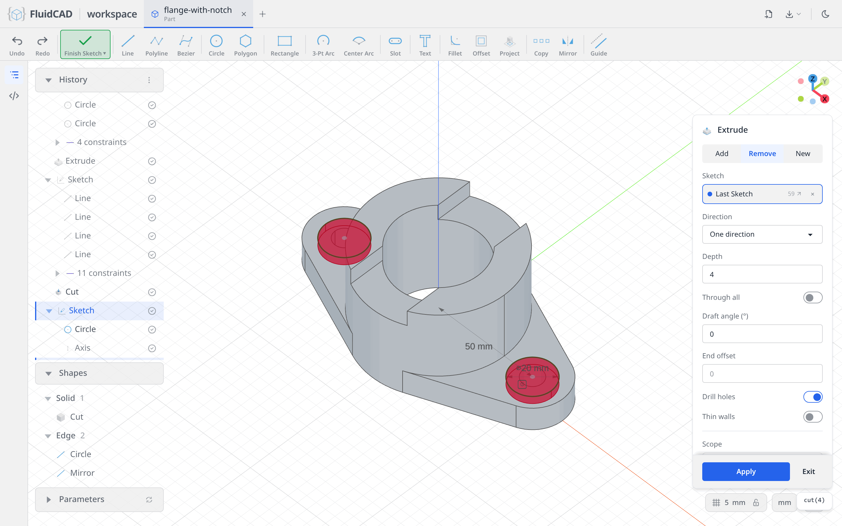
Click Apply. That is the flange.
Full code
Everything above was written into flange-with-notch.fluid.js by the dialogs. Open the code editor with the </> button on the left rail or Ctrl+B to read it. The listing below is the same model with tidier names; the coordinates you clicked will differ, but the constraints make the geometry identical.
Show the full code
// @screenshot waitForInput
import { arc, circle, cut, extrude, line, mirror, origin, sketch, xAxis, yAxis } from "fluidcad/core";
import { coincident, concentric, diameter, distance, horizontal, midpoint, radius,
    symmetric, tangent, vertical } from "fluidcad/constraints";

sketch('xy', () => {
  const outer = circle([0, 0], 70);
  const bore = circle([0, 0], 42);
  const hole = circle([50, 0], 10);
  const upper = line([15, 30], [55, 15]);
  const lower = line([15, -30], [55, -15]);
  const cap = arc([55, -15], [55, 15], [42, 0]);
  coincident(outer.center(), origin());
  diameter(outer, 70);
  coincident(bore.center(), origin());
  diameter(bore, 42);
  coincident(hole.center(), xAxis());
  diameter(hole, 10);
  distance(hole.center(), yAxis(), 50);
  coincident(cap.start(), lower.end());
  coincident(cap.end(), upper.end());
  tangent(upper, outer);
  coincident(upper.start(), outer);
  concentric(cap, hole);
  radius(cap, 16);
  tangent(upper, cap);
  symmetric(upper.start(), lower.start(), xAxis());
  tangent(lower, cap);
  mirror(yAxis(), upper, cap, lower, hole);
});

const flange = extrude(12);

sketch(flange.endFaces(), () => {
  const wall = circle([0, 0], 70);
  const inner = circle([0, 0], 42);
  coincident(wall.center(), origin());
  diameter(wall, 70);
  coincident(inner.center(), origin());
  diameter(inner, 42);
});

const pipe = extrude(34);

sketch(pipe.endFaces(), () => {
  const bottom = line([-15, -35], [15, -35]);
  const right = line([15, -35], [15, 35]);
  const top = line([15, 35], [-15, 35]);
  const left = line([-15, 35], [-15, -35]);
  coincident(bottom.end(), right.start());
  coincident(right.end(), top.start());
  coincident(top.end(), left.start());
  coincident(left.end(), bottom.start());
  horizontal(bottom);
  horizontal(top);
  vertical(right);
  vertical(left);
  distance(bottom.start(), bottom.end(), 30);
  distance(right.start(), right.end(), 70);
  midpoint(origin(), bottom.start(), top.start());
});

cut(8);

sketch(flange.endFaces(), () => {
  const recess = circle([50, 0], 20);
  diameter(recess, 20);
  distance(recess.center(), yAxis(), 50);
  coincident(recess.center(), xAxis());
  mirror(yAxis(), recess);
});

cut(4);
What you practiced
- Circle snapped to the origin or an axis, and Dimension against the sketch's own axes instead of typed coordinates
- A rough outline (Line, Line, 3-Pt Arc) turned into an exact one by Tangent, Concentric, a typed radius and Symmetric, with the DOF pill as the check that nothing is left loose
- The 2D Mirror tool, twice, for the second tab and the second counterbore
- Sketching on a face an operation produced, and reading the Face — Extrude / Face — Cut chip
- Rectangle with its Centered option, one gesture for a fully constrained notch profile
- Extrude on the Remove tab with a typed depth, for cuts that stop part way through