Building a Fork
In this tutorial you'll build a forked yoke, based on the original design by TooTallToby. You build it entirely from the FluidCAD workspace: the toolbar, the sketch tools, the constraint bar and the feature dialogs. Every dialog writes a line of code into your file as you apply it, so the full code at the end is what the UI produced, not something you type.
It covers a silhouette sketched from two arcs and three lines, the 2D Mirror tool, dimensioning against the sketch's own axes, a symmetric extrusion, a construction plane at an offset, mirroring a whole feature with Repeat, projecting a model edge in as a fixed reference, the Polygon tool, and the Thin walls option on a Remove extrude — a ring of material cut away to leave the shape inside it standing.
Before you start
Open a workspace and create a new part file: click + in the top bar and type fork.fluid.js. The new tab opens on an empty scene. The screenshots use the light theme; the sun/moon button at the top right switches it.
A few UI habits you will use throughout:
- Ctrl+click adds an entity to the current selection. A plain click replaces it.
- The constraint bar appears under the toolbar while you sketch. Its buttons are icons; hover one for its name. A button lights up only when the current selection makes sense for it.
- Dimension is one button. What it writes depends on what you picked: an arc alone gives a radius, a circle a diameter, a point and an axis a distance.
- The DOF pill at the bottom of the viewport counts the degrees of freedom left in a sketch and turns into Fully constrained when you are done.
- Every feature dialog shows the statement it is about to write, just under the dialog. Apply (or Enter) writes it; Exit / Cancel (or Escape) discards it.
- Inside a sketch, N looks straight down the sketch plane.
Step 1: The fork silhouette
The whole side view of the part is one sketch: a semicircular arch wall, a leg hanging off each end of it, and a column standing on top. Extruded symmetrically, that is the body.
Start a sketch on the XZ plane
Click Sketch in the toolbar. The dialog asks for a face or a plane, and the three origin planes appear in the viewport.
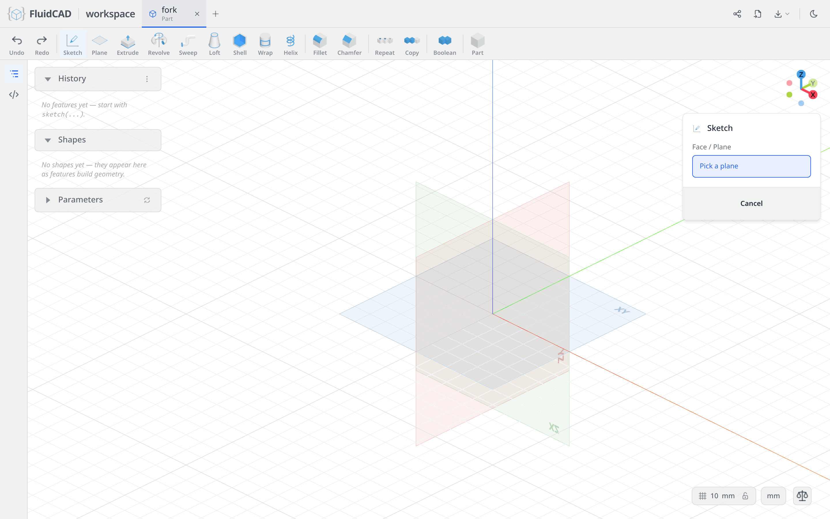
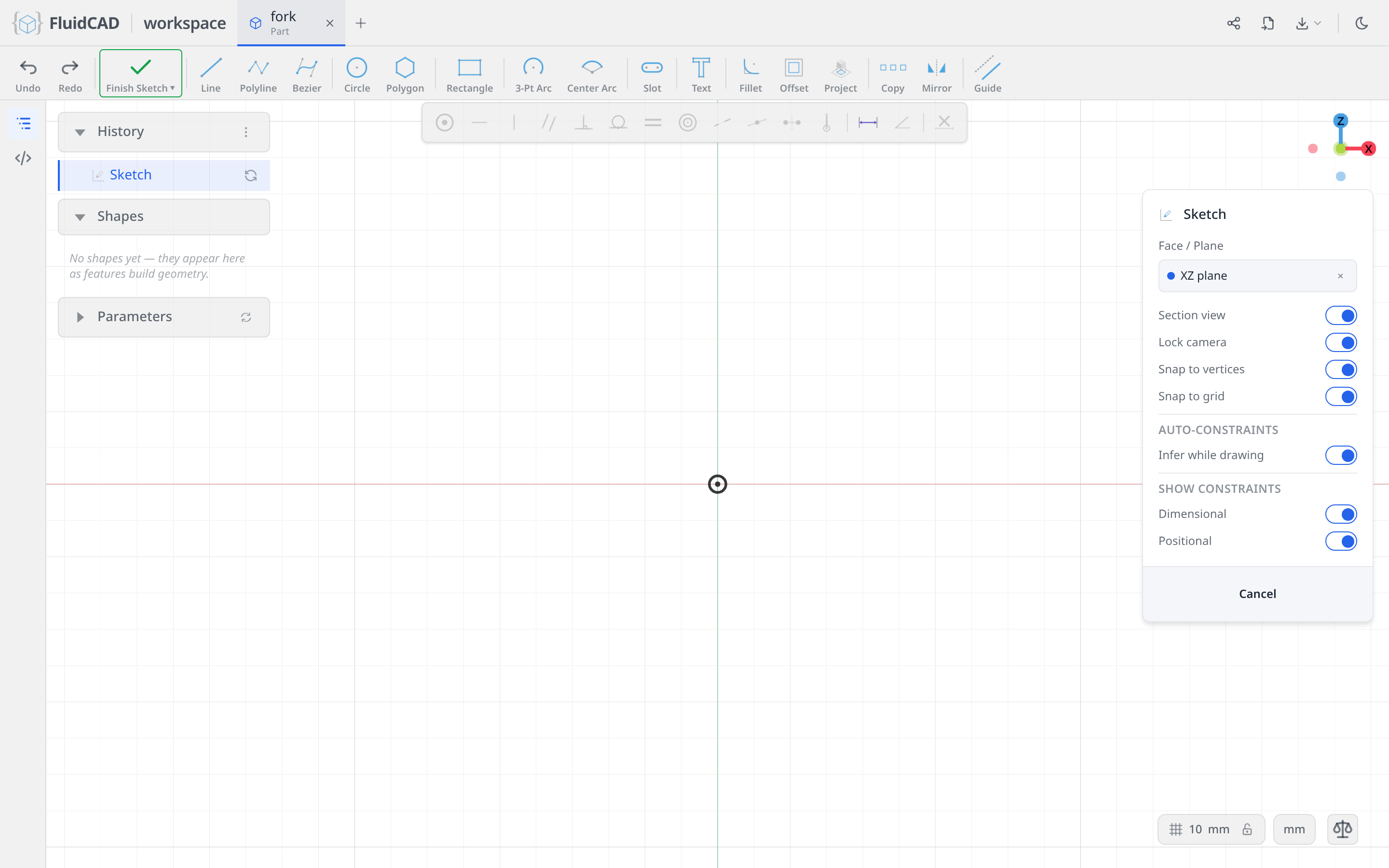
Click the XZ plane — the one that stands upright facing you. The camera locks onto it, the sketch toolbar replaces the feature toolbar, and the constraint bar appears above the viewport.
Sweep the two arcs of the arch wall
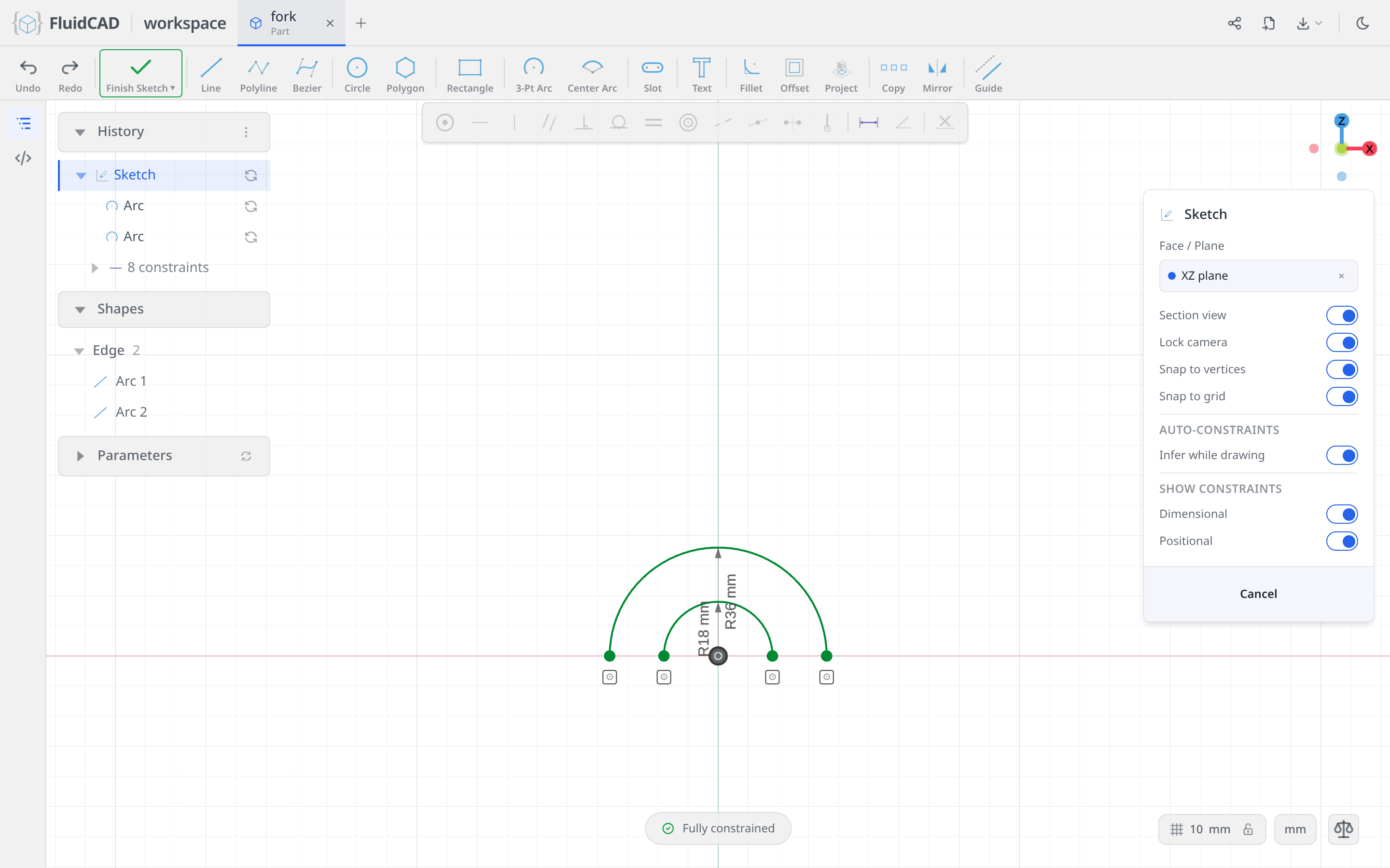
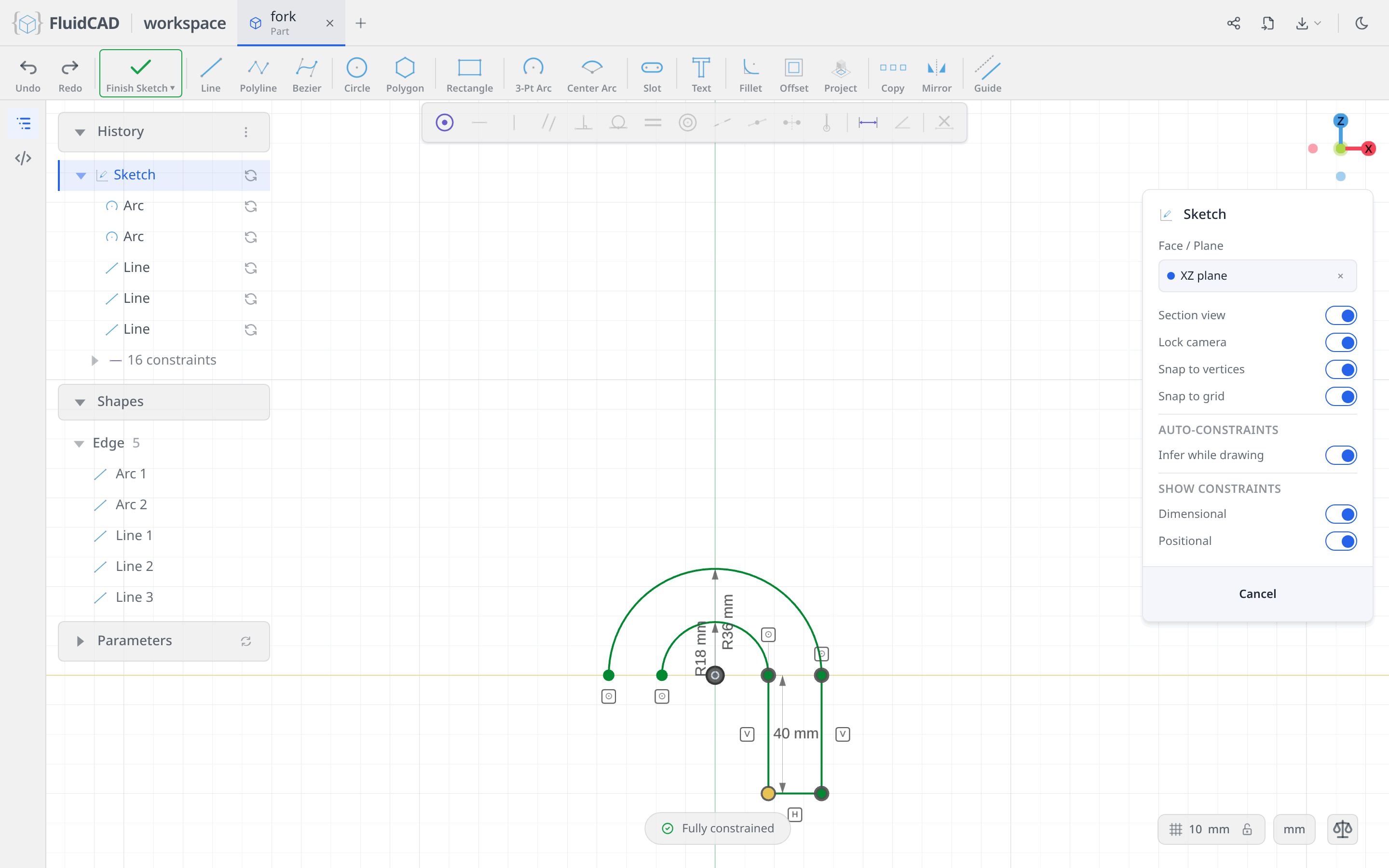
The arch is a wall 18 thick: an R18 bore inside, an R36 back outside, both centred on the origin.
Pick Center Arc. Click the origin for the centre, click a point out along the horizontal axis for the start, then sweep up and over to the left. A ∠ readout follows the mouse; type 180 and press Enter for exactly half a circle.
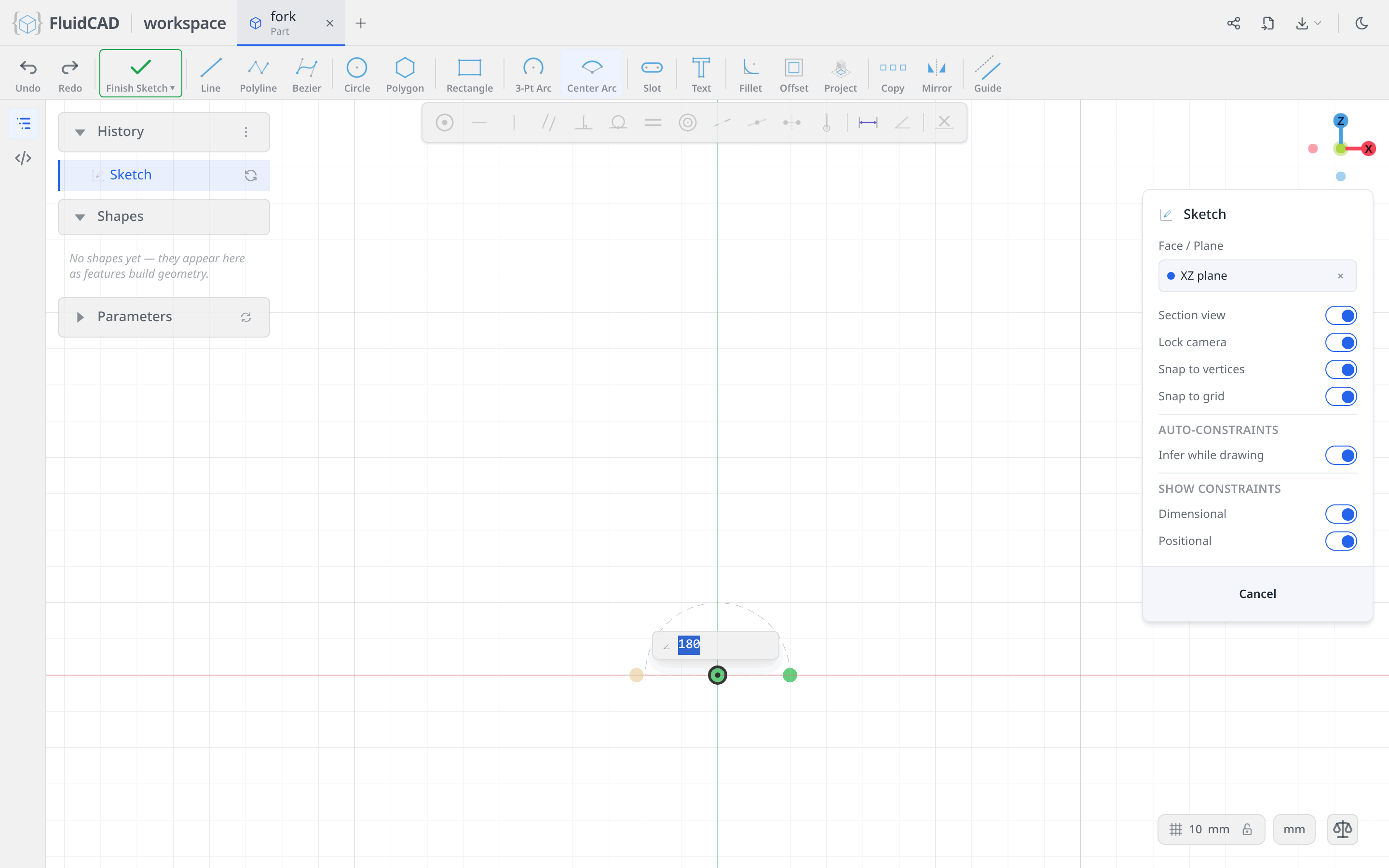
Because you clicked the origin and started on the axis, the arc arrives with its centre pinned to the origin and both ends held on the horizontal axis. Only the radius is left: click the arc, click Dimension and type 18.
Do the same again for the outer wall — Center Arc, origin, a start further out along the axis, 180, then Dimension 36. Both centres landed on the origin, so the two arcs are concentric without you saying so, and the DOF pill reads Fully constrained.
Hang the right leg off the arch
The leg is three lines, and each one starts on something that already exists — so the sketch stays almost fully described as you draw.
Pick Line. Draw the first line from the end of the inner arc straight down; snap to that endpoint and it arrives with a coincident and a vertical on it. Draw the second the same way from the end of the outer arc. Then draw the third from the bottom of one to the bottom of the other — both ends snap, so it comes with two coincidents and a horizontal.
One degree of freedom is left: how far down the leg reaches. Click the bottom-left corner, Ctrl+click the horizontal axis, and click Dimension. Type 40.
Mirror the leg
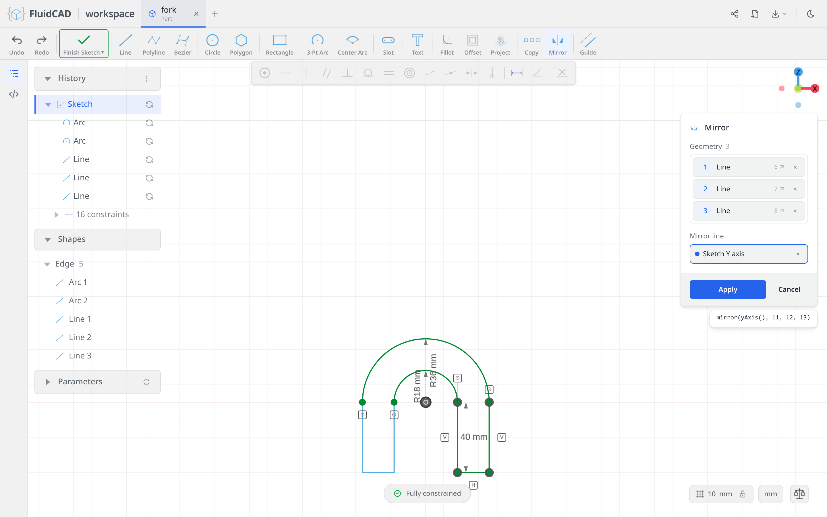
Click a blank spot to clear the selection, then click the leg's three lines — one, then Ctrl+click the other two. Click Mirror in the sketch toolbar. The three lines land in the Geometry list.
Click the Mirror line slot to arm it, then click the sketch's vertical axis in the viewport. The slot reads Sketch Y axis.
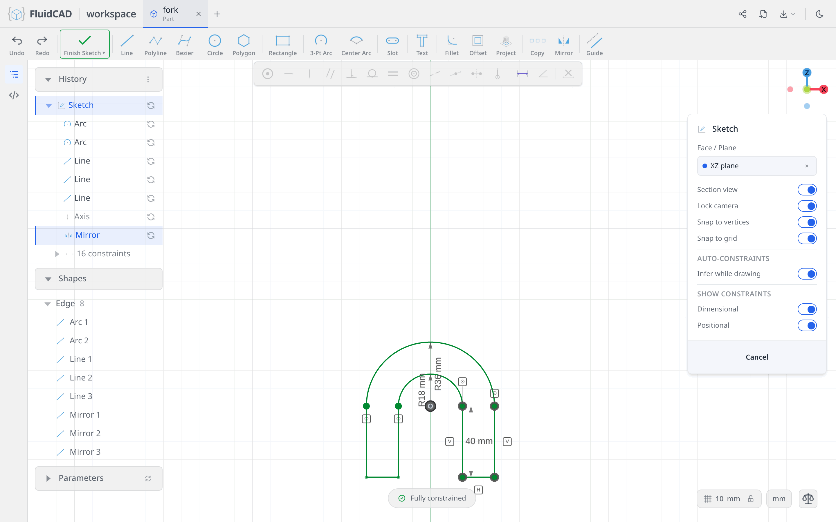
Click Apply. The left leg appears, and with it the outline closes: outer arc, left leg, inner arc, right leg.
Add the column
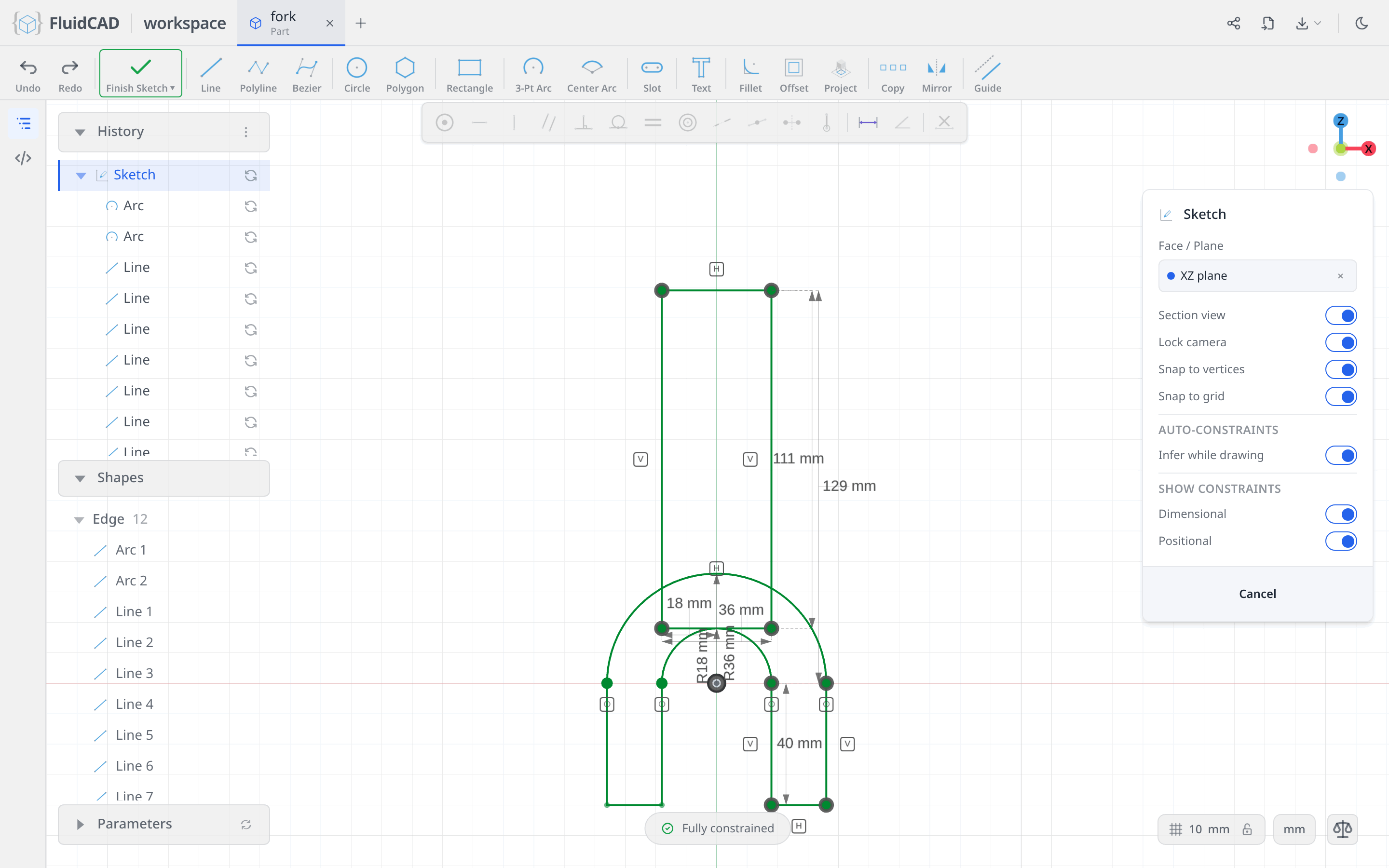
The column is a plain rectangle overlapping the arch — a second closed region in the same sketch. The extrude fuses the two.
Pick Rectangle. Click a first corner somewhere above and left of the arch, type 36 for W and Enter, then 111 for H and Enter. (129 is the height of the finished part above the arch centreline, and 18 of that is the bore, so the column itself is 111 tall — its bottom edge grazes the top of the bore and is buried in the arch wall.)
Two degrees of freedom are left, so place the rectangle with two dimensions:
- Click the bottom-left corner, Ctrl+click the vertical axis, Dimension,
18. Half of 36 — that centres the column. - Click the top-right corner, Ctrl+click the horizontal axis, Dimension,
129.
The pill reads Fully constrained.
Extrude the body
Everything a sketch can become stays on the toolbar while the sketch is open. Click Extrude. Set Direction to Symmetric and Total distance to 36. Symmetric splits the distance evenly across the sketch plane, so 18 goes each way and the part is centred on the plane you drew it on. The green ghost is the live preview and the statement reads extrude(36).symmetric().
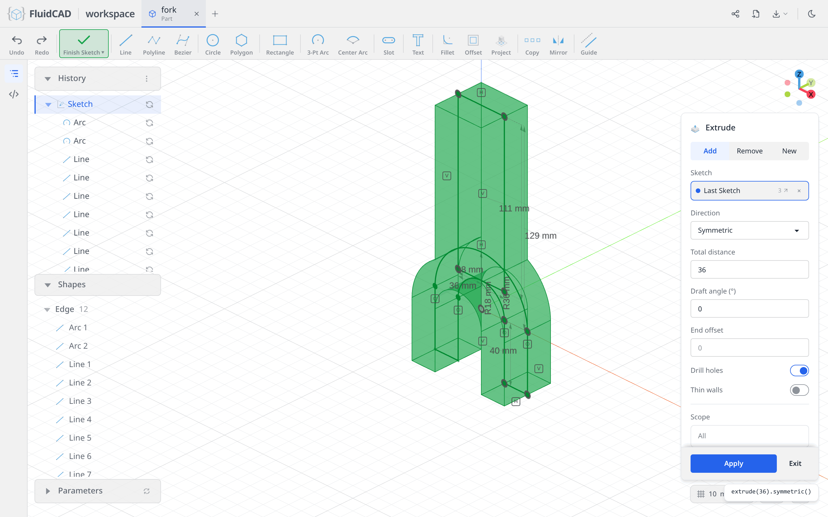
Click Apply.
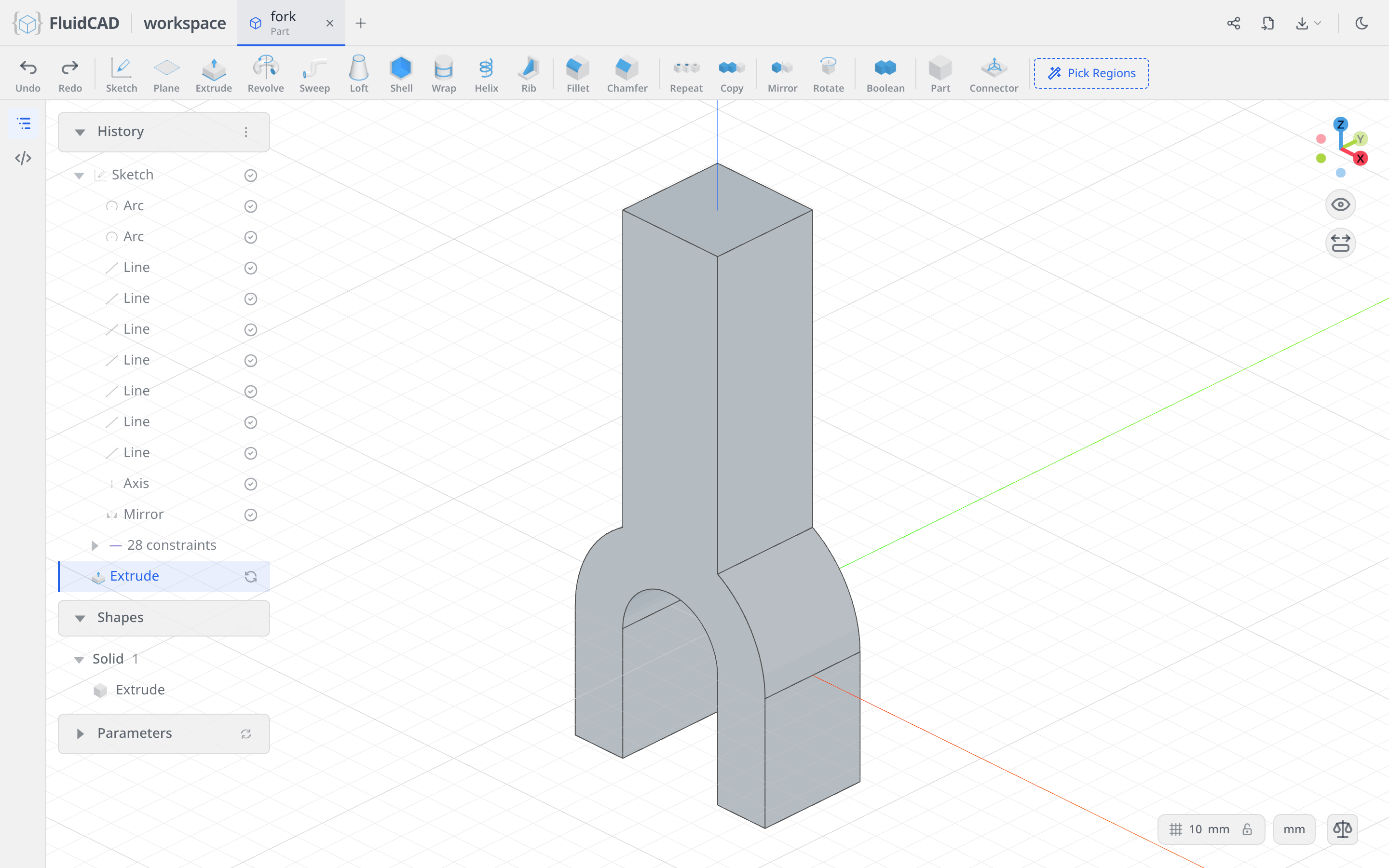
Step 2: The side bosses
Each leg carries a ⌀60 boss on its outside. The boss is bigger than the leg it grows from, so it cannot be sketched on the leg's own face — it needs a plane of its own, standing where the leg begins.
A construction plane 18 out from the centre
Click Plane in the toolbar. Leave Type on Offset, click the YZ plane for the base, and set Offset to 18. That is the inside face of the right leg. A yellow ghost quad shows where the plane will sit, and the statement reads plane('yz', 18).
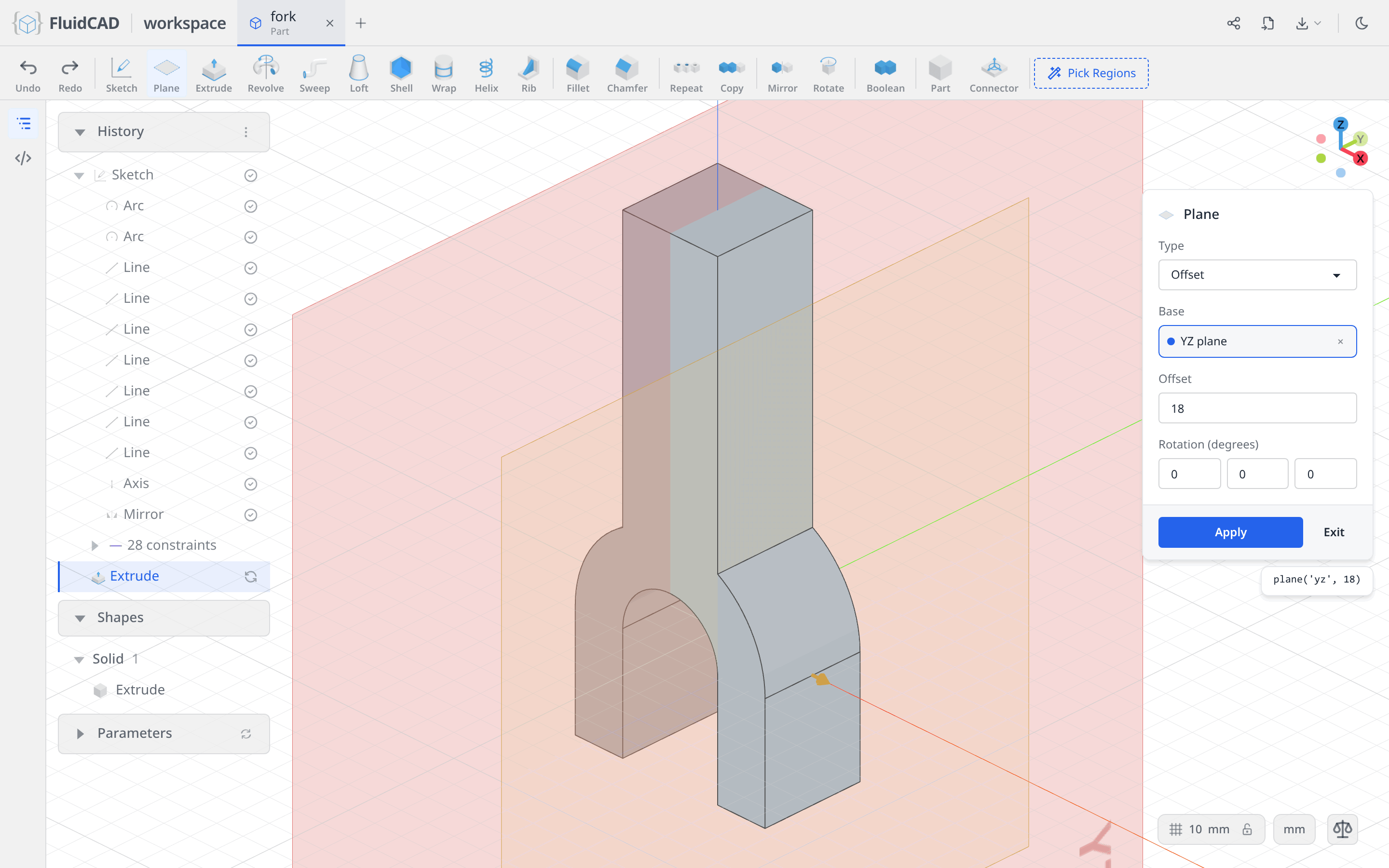
Click Apply.
Sketch the boss circle
Click Sketch and click the new plane. Because the plane cuts through the part, Section view clips the near half away and you see the leg in cross-section.
Pick Circle. Click a point on the vertical axis below the origin for the centre — snapping to the axis is what pins it sideways — then type 60 for the ⌀ readout and press Enter.
One degree of freedom is left. Click the centre point, Ctrl+click the horizontal axis, click Dimension and type 38.

Extrude it, then mirror the feature
Click Extrude on the toolbar. Set Distance to 22. The plane already stands 18 out from the centreline, and the finished part is 80 across the two bosses, so the boss has 40 − 18 = 22 left to travel.
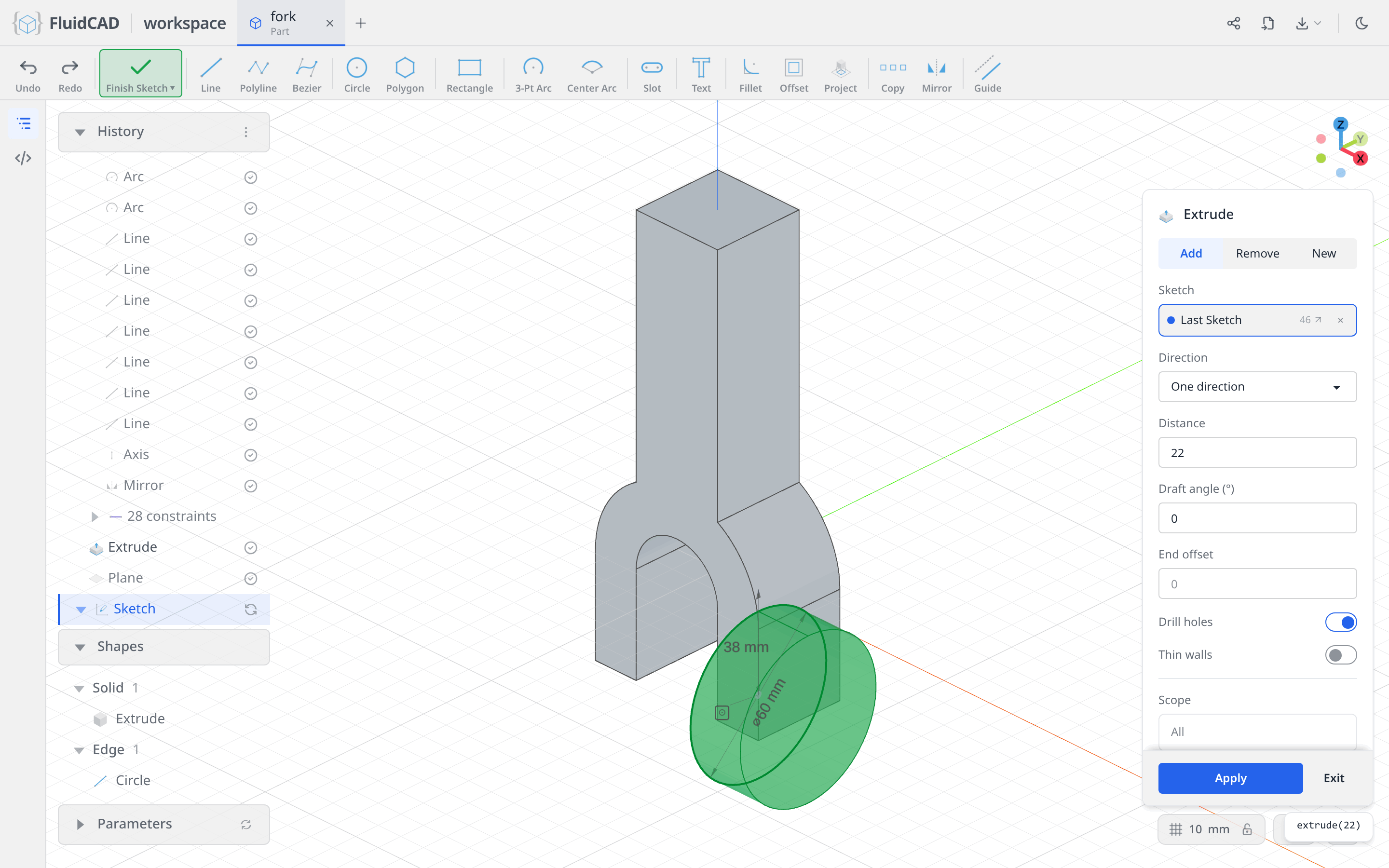
Click Apply, then click Repeat in the toolbar and set Type to Mirror. Repeat takes its targets from the History panel: click the Extrude row you just made, and it lands in the Features slot. Then click the Plane slot and click the YZ plane in the viewport. The ghost shows the second boss and the statement reads repeat('mirror', 'yz', f).
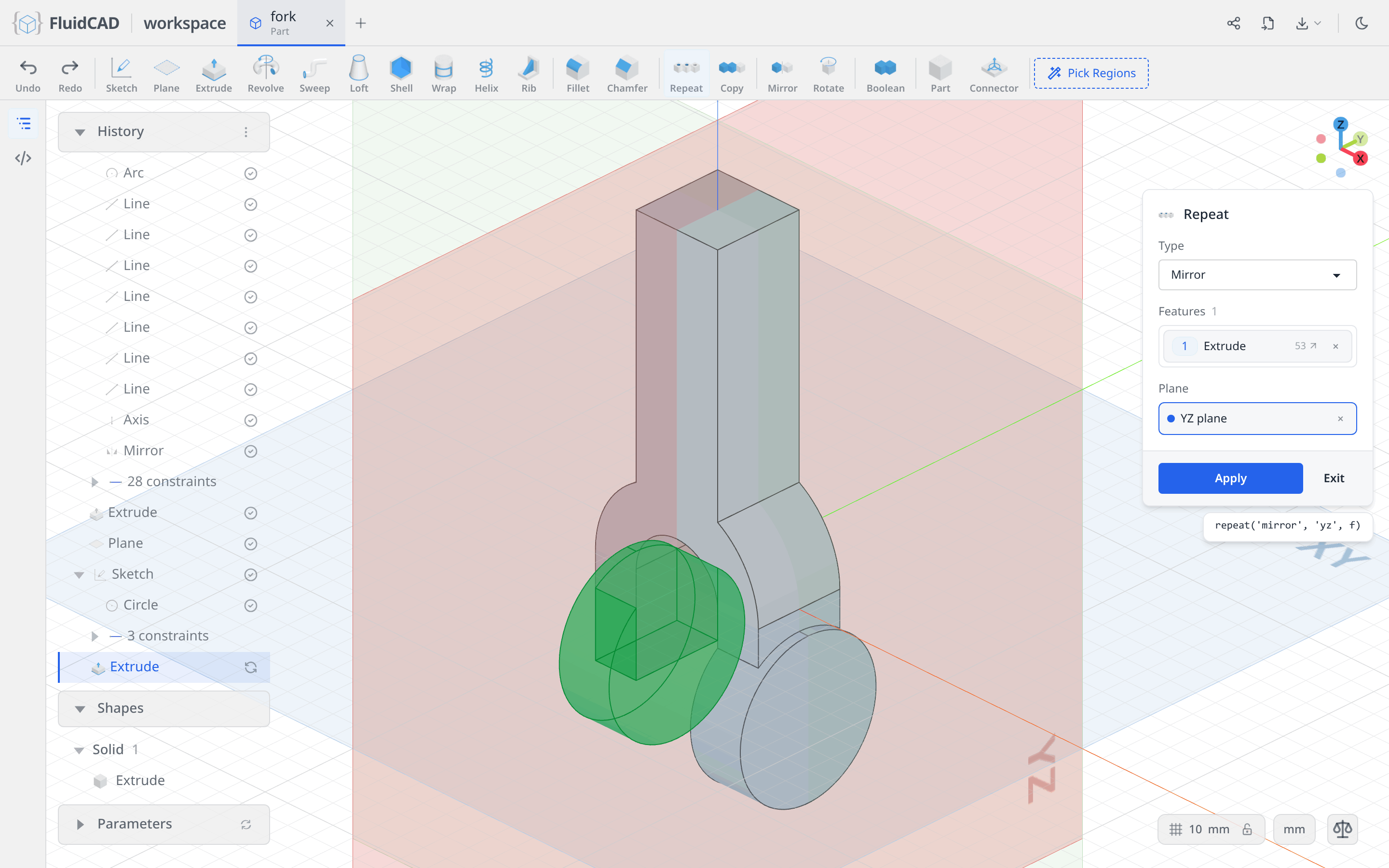
Click Apply. Repeat mirrors the operation, so the second boss grows out of the left leg the same way the first grew out of the right.
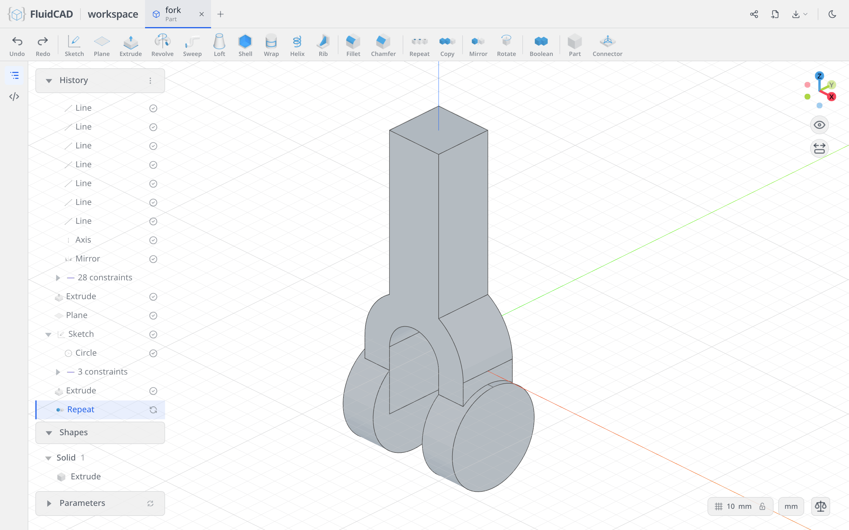
Step 3: Bore through the bosses
One ⌀30 hole runs through both bosses. Sketch it on the flat outer face of one of them.
Sketch on the boss face, with its rim projected in
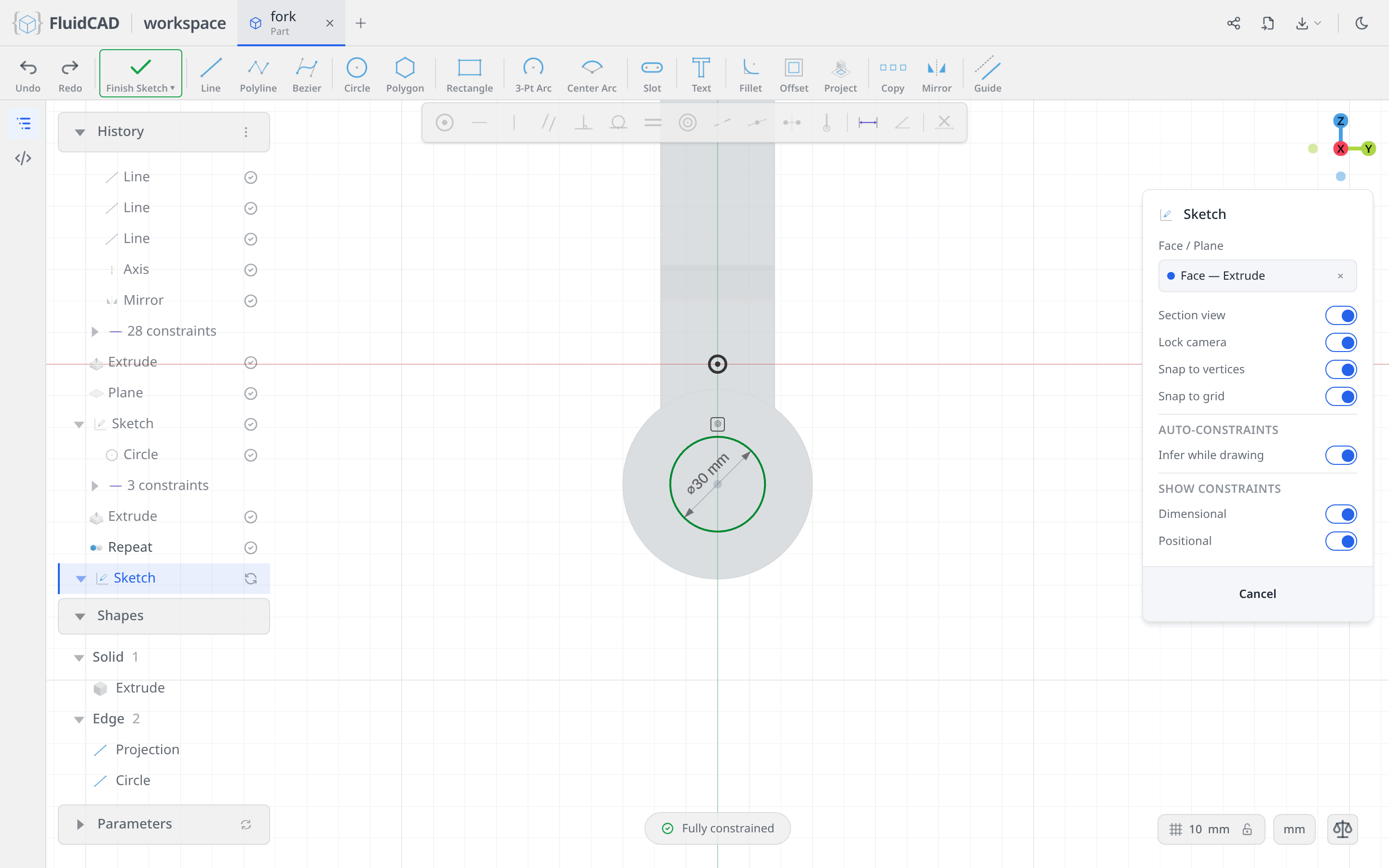
Click Sketch and click the flat outer face of the right boss. The chip reads Face — Extrude: FluidCAD remembered which operation produced that face, so the sketch follows the boss if you change it later.
A face sketch has its own axes, and they do not run through the boss centre — so instead of measuring to the hole, bring the boss's own rim into the sketch and hang the hole off that. Pick Project and click the circular edge of the face. The statement reads project(f.startEdges(edge().arc())).
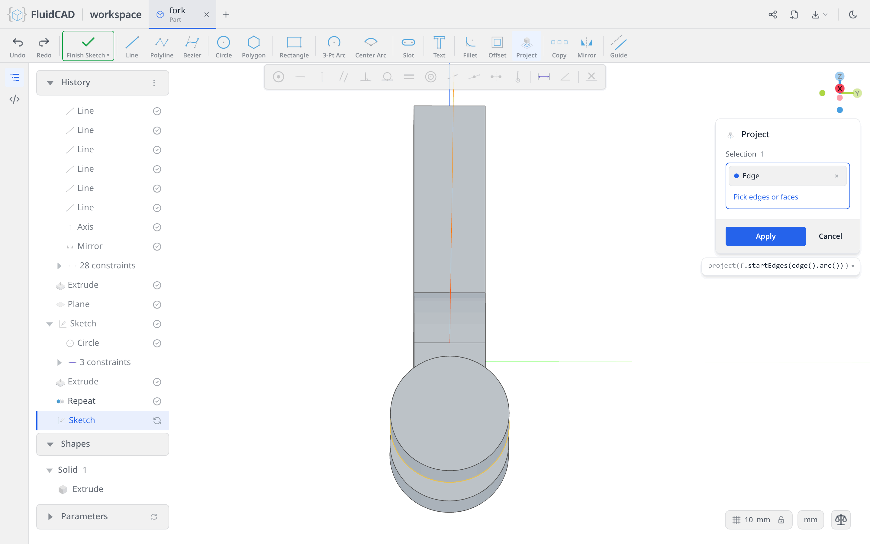
Click Apply. The rim is now a fixed circle inside the sketch.
Draw the bore against it
Pick Circle and drop one roughly inside the rim; type 30 for the ⌀. Two degrees of freedom are left — where the circle sits.
Click the new circle, Ctrl+click the projected rim, and click Concentric.
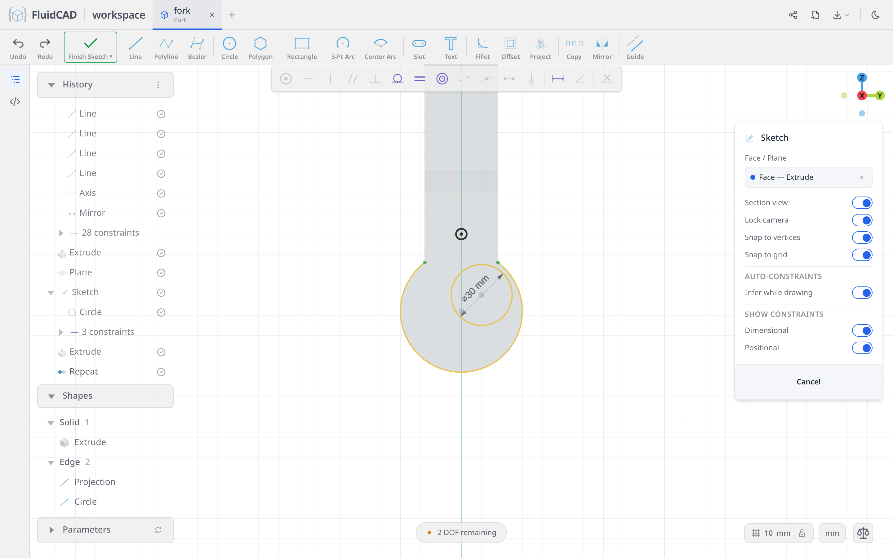
That is the last of it: Fully constrained, and the bore is on the boss axis by construction rather than by a number you typed.
The rim has done its job, so demote it: click it and hit Guide. That appends .guide() to the projection, which turns it into construction geometry — still there to hold the concentric, but no longer a profile the cut could pick up.
Cut through everything
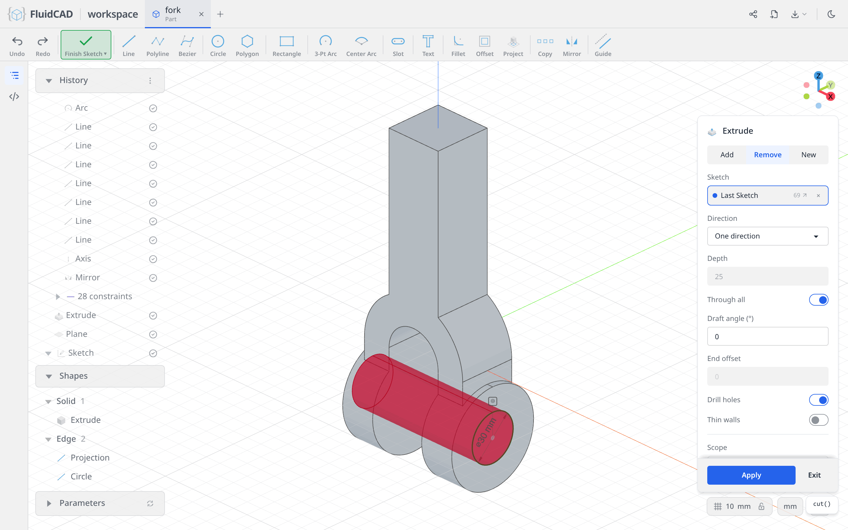
Click Extrude on the toolbar. Select the Remove tab and switch on Through all. The red ghost is the material about to disappear — a rod running through both bosses — and the statement is simply cut().
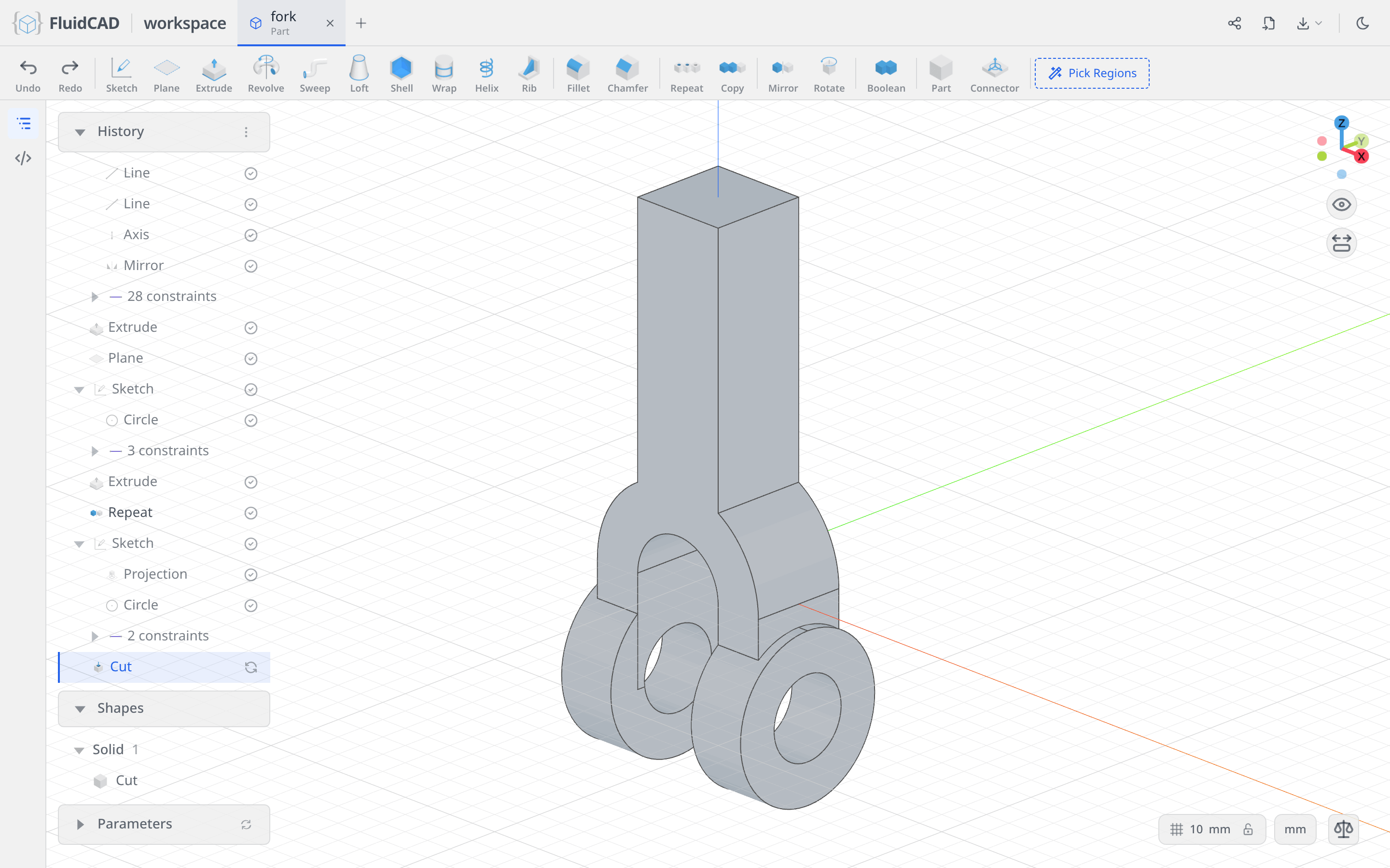
Click Apply.
Step 4: The cylindrical post
The top of the column steps down twice. Both steps use the same trick: sketch the shape you want to keep, then cut a thick ring around it.
Sketch the post circle
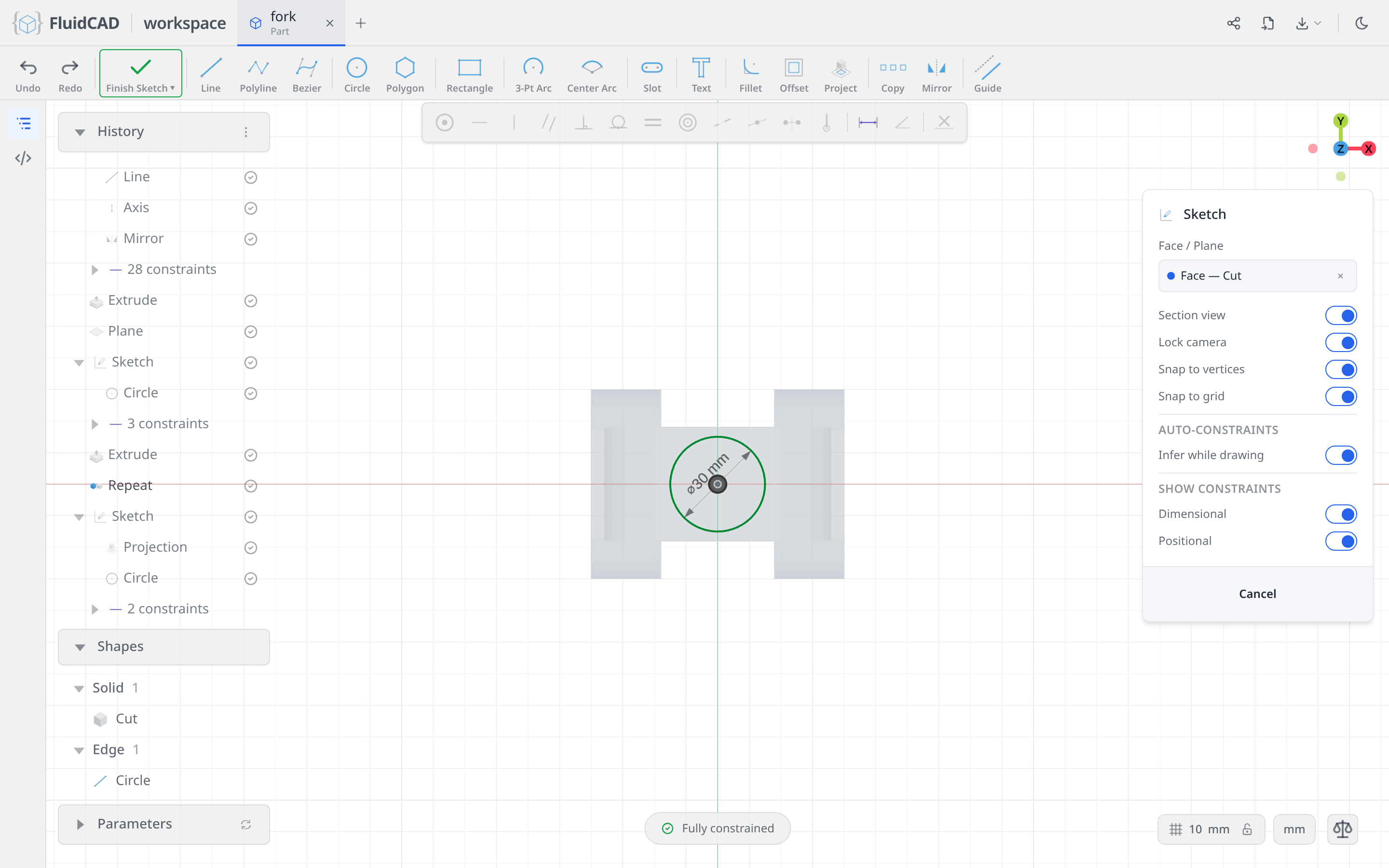
Click Sketch and click the top face of the column. Looking straight down, the section view shows the part underneath.
Pick Circle, click the origin for the centre, and type 30 for the ⌀. Clicking the origin pins the centre, so the sketch is Fully constrained the moment the diameter lands.
Cut a 20-thick ring around it
Click Extrude on the toolbar. Select the Remove tab, set Depth to 20, and switch on Thin walls with a Thickness of 20.
Thin walls turns the profile from an area into a wall: instead of removing the disc, the cut removes a 20-wide ring hugging the outside of it. The ring reaches 35 from the centre — further than the corners of the 36 square column — so it sweeps everything away except the cylinder in the middle. The statement reads cut(20).thin(20).
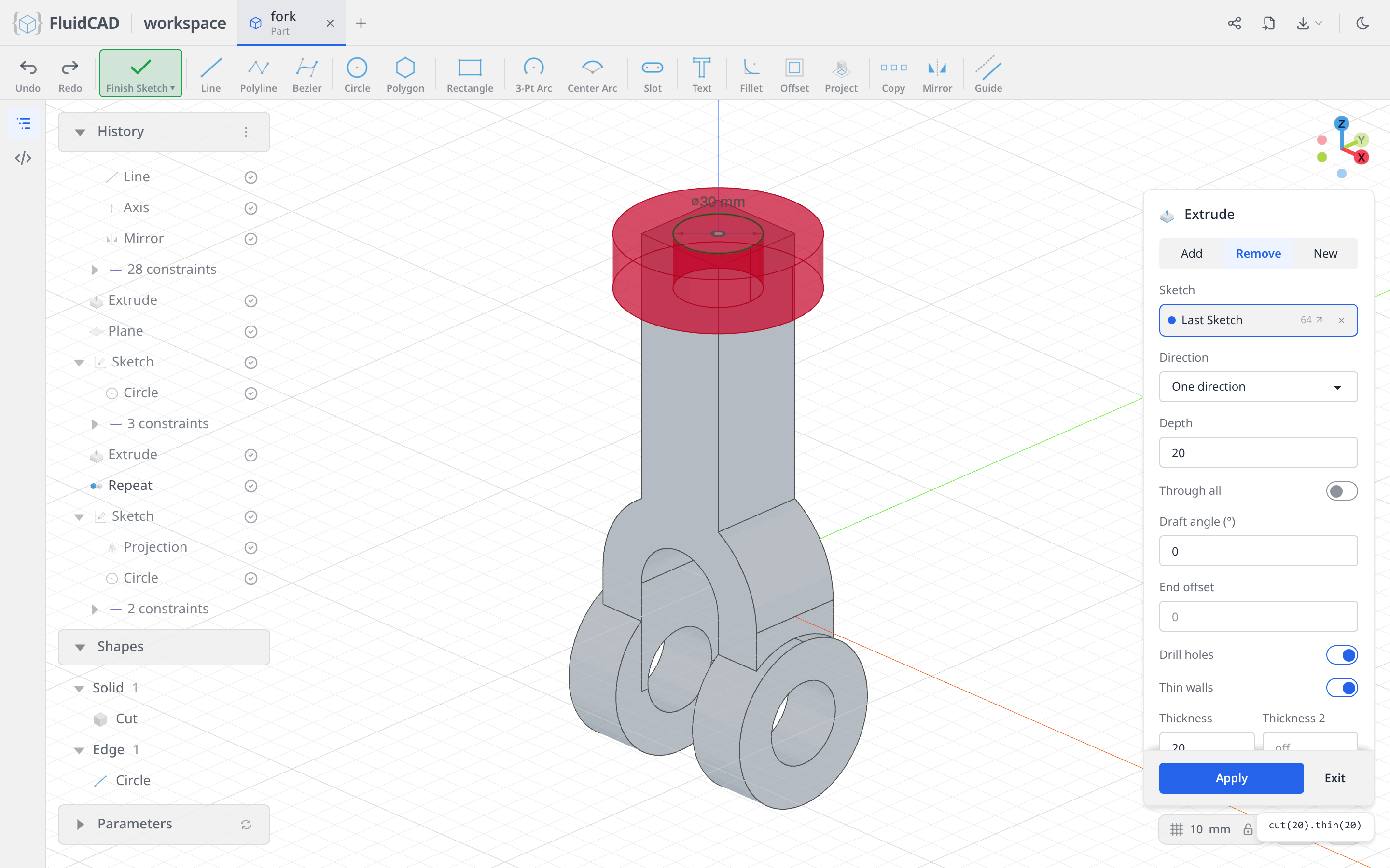
Click Apply.
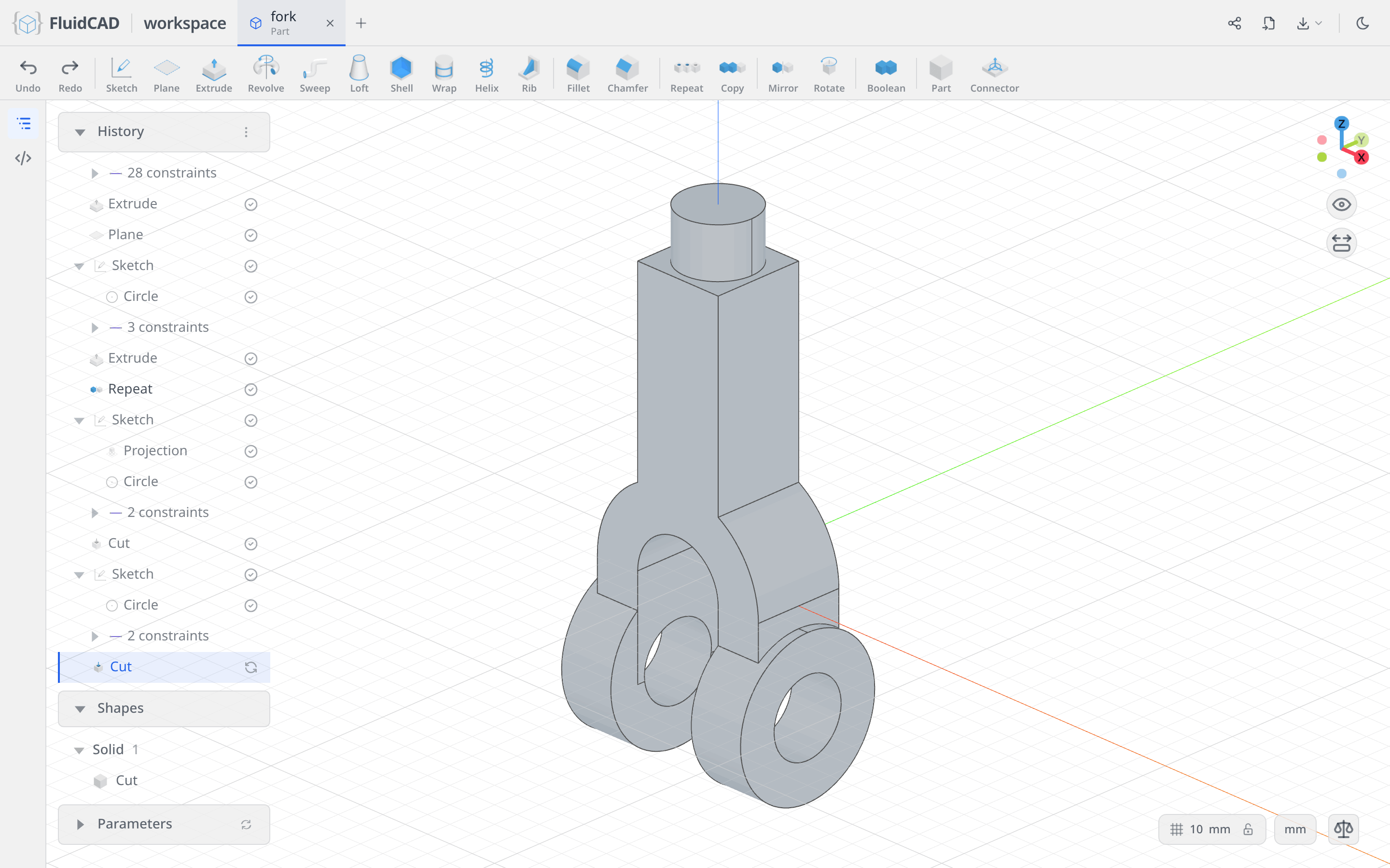
Step 5: The square section
The same trick with a different profile leaves a square section between the post and the body — and a square is one tool, not four lines.
Sketch the square with the Polygon tool
Click Sketch and click the flat face left around the post — the step the last cut created. Pick Polygon. Click the origin for the centre, type 36 for the ⌀ readout, press Enter, then type 4 for N.
The Polygon tool is circumscribed by default, so the 36 is measured across the flats: it emits four lines, a coincident at every corner, an equal on the sides, a tangent from each side to a ⌀36 guide circle, one 90° angle and the guide circle's diameter. One degree of freedom is left — the polygon can still spin, however square it happens to look.
Click the corner on the right, Ctrl+click the horizontal axis, and click Coincident. That is the design intent: a 36 square turned 45°, corners on the axes.
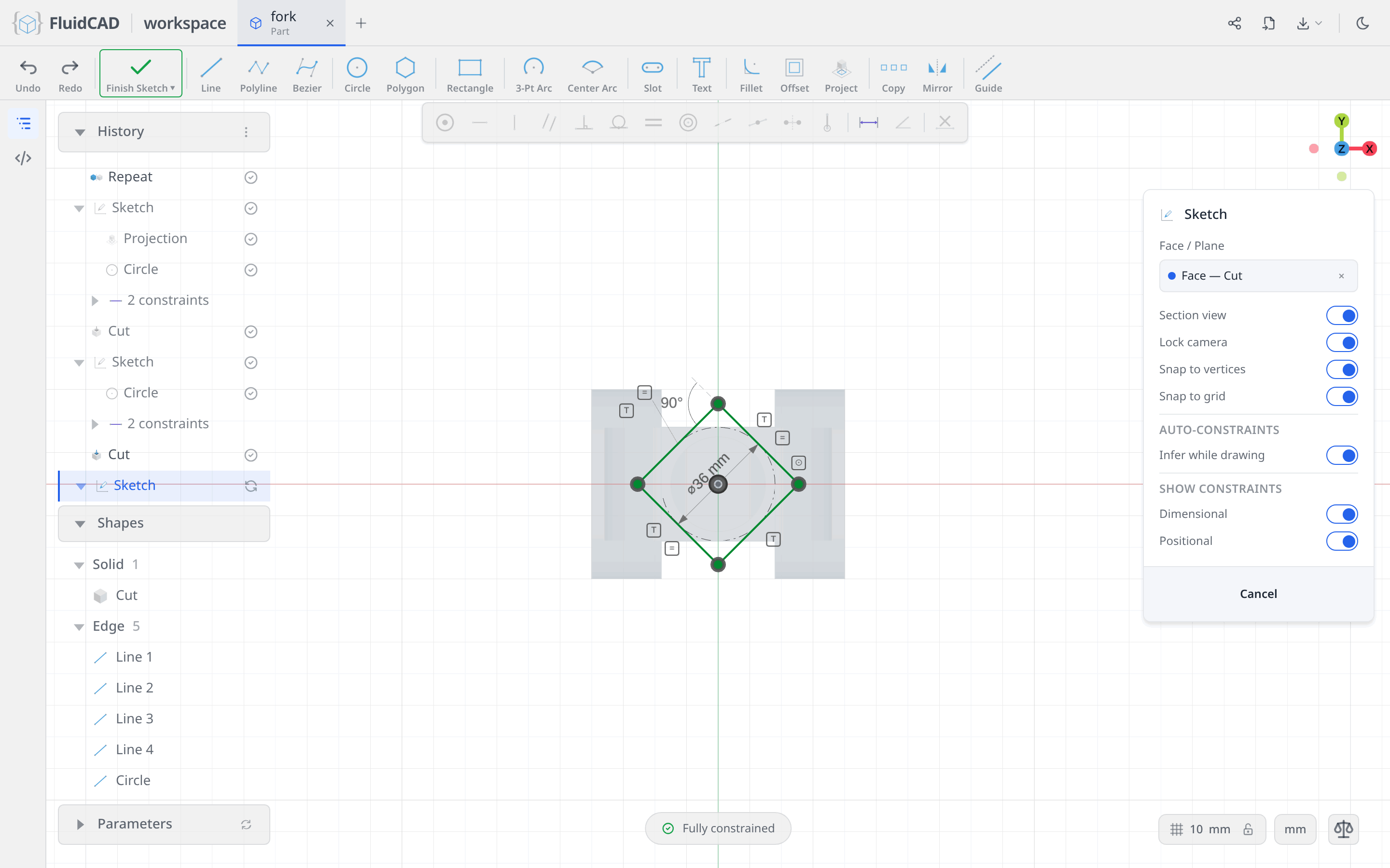
Cut the ring around it
Click Extrude on the toolbar. Remove tab, Depth 45, Thin walls on with Thickness 20. The statement reads cut(45).thin(20).
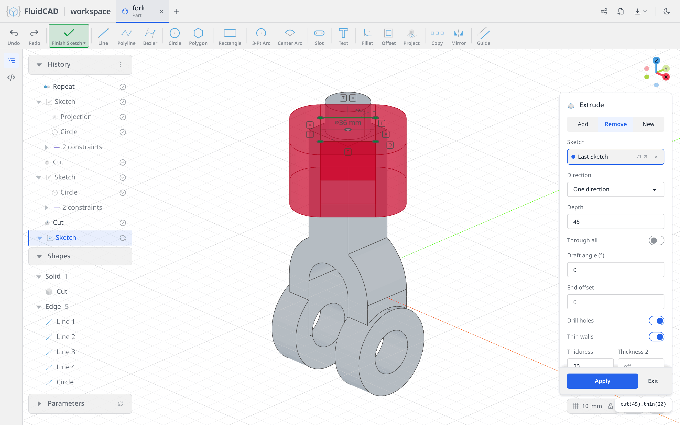
Click Apply. The corners of the column are sliced away over those 45, leaving a square cross-section that meets the body below and the post above.
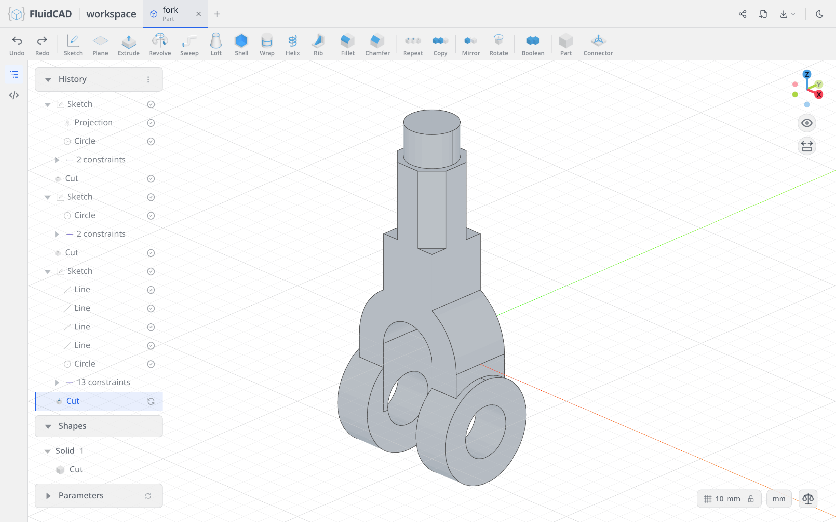
Full code
Everything above was written into fork.fluid.js by the dialogs. Open the code editor with the </> button on the left rail or Ctrl+B to read it. The listing below is the same model with tidier names; the coordinates you clicked will differ, but the constraints make the geometry identical.
Show the full code
// @screenshot waitForInput
import { arc, circle, cut, extrude, line, mirror, origin, plane, project, repeat,
    sketch, xAxis, yAxis } from "fluidcad/core";
import { angle, coincident, concentric, diameter, distance, equal, horizontal,
    radius, tangent, vertical } from "fluidcad/constraints";
import { edge } from "fluidcad/filters";

sketch("xz", () => {
    // Arch wall: two semicircles centred on the origin, R18 inside, R36 outside
    const inner = arc([18, 0], [-18, 0], [0, 0]);
    const outer = arc([36, 0], [-36, 0], [0, 0]);
    coincident(inner.center(), origin());
    coincident(inner.start(), xAxis());
    coincident(inner.end(), xAxis());
    radius(inner, 18);
    coincident(outer.center(), origin());
    coincident(outer.start(), xAxis());
    coincident(outer.end(), xAxis());
    radius(outer, 36);

    // Right leg: three lines hanging from the two ends of the arch wall
    const legInner = line([18, 0], [18, -40]);
    const legOuter = line([36, 0], [36, -40]);
    const legBottom = line([18, -40], [36, -40]);
    coincident(legInner.start(), inner.start());
    vertical(legInner);
    coincident(legOuter.start(), outer.start());
    vertical(legOuter);
    coincident(legBottom.start(), legInner.end());
    coincident(legBottom.end(), legOuter.end());
    horizontal(legBottom);
    distance(legInner.end(), xAxis(), 40);

    // Column: 36 wide, its top face 129 above the arch centreline
    const colBottom = line([-18, 18], [18, 18]);
    const colRight = line([18, 18], [18, 129]);
    const colTop = line([18, 129], [-18, 129]);
    const colLeft = line([-18, 129], [-18, 18]);
    coincident(colBottom.end(), colRight.start());
    coincident(colRight.end(), colTop.start());
    coincident(colTop.end(), colLeft.start());
    coincident(colLeft.end(), colBottom.start());
    horizontal(colBottom);
    horizontal(colTop);
    vertical(colRight);
    vertical(colLeft);
    distance(colBottom.start(), colBottom.end(), 36);
    distance(colRight.start(), colRight.end(), 111);
    distance(colBottom.start(), yAxis(), 18);
    distance(colTop.start(), xAxis(), 129);

    mirror(yAxis(), legInner, legOuter, legBottom);
});

const body = extrude(36).symmetric();

const bossPlane = plane("yz", 18);

sketch(bossPlane, () => {
    const disc = circle([0, -38], 60);
    coincident(disc.center(), yAxis());
    diameter(disc, 60);
    distance(disc.center(), xAxis(), 38);
});

const boss = extrude(22);

repeat("mirror", "yz", boss);

sketch(boss.endFaces(), () => {
    const rim = project(boss.startEdges(edge().arc())).guide();
    const bore = circle([0, -38], 30);
    diameter(bore, 30);
    concentric(bore, rim);
});

cut();

sketch(body.sideFaces(6), () => {
    const post = circle([0, 0], 30);
    coincident(post.center(), origin());
    diameter(post, 30);
});

const postStep = cut(20).thin(20);

sketch(postStep.internalFaces(0), () => {
    // What the Polygon tool wrote: four equal sides tangent to a 36 guide circle
    const s1 = line([25.46, 0], [0, 25.46]);
    const s2 = line([0, 25.46], [-25.46, 0]);
    const s3 = line([-25.46, 0], [0, -25.46]);
    const s4 = line([0, -25.46], [25.46, 0]);
    const guide = circle([0, 0], 36).guide();
    coincident(s1.end(), s2.start());
    coincident(s2.end(), s3.start());
    coincident(s3.end(), s4.start());
    coincident(s4.end(), s1.start());
    equal(s1, s2, s3);
    tangent(s1, guide);
    tangent(s2, guide);
    tangent(s3, guide);
    tangent(s4, guide);
    angle(s1, s2, 90);
    diameter(guide, 36);
    coincident(guide.center(), origin());
    coincident(s1.start(), xAxis());
});

cut(45).thin(20);
What you practiced
- Center Arc with a typed included angle, and two arcs made concentric just by clicking the same centre
- Drawing from what is already there — every line started on an existing endpoint, so it arrived with its coincidents and its horizontal or vertical already written
- The 2D Mirror tool across the sketch's own Y axis, and Repeat → Mirror across a datum plane for a whole feature
- Dimension against the sketch axes instead of typed coordinates, with the DOF pill as the check that nothing is left loose
- Two overlapping closed regions in one sketch, fused by a single symmetric extrude
- A construction plane at an offset, for a boss too big to sketch on the face it grows from
- Project, to bring a model edge into a face sketch, Concentric against it, then Guide to demote it to construction geometry
- Polygon, circumscribed, for a square described by one diameter and one angle
- Thin walls on a Remove extrude — cutting a ring around a profile to leave the shape inside it standing