Building a Gear Housing
In this tutorial, you'll build a gear housing based on exercises from Too Tall Toby. It covers constraint sketches, filleting, angled chamfers, multi-level extrusions, draft cuts, arc profiles, rounded-corner profiles, drilling, counterbores, circular copy patterns, and mirror symmetry.
Create a new file called gear-housing.fluid.js in your project.
Setup
Start with the imports and parameters for the support brackets:
import { arc, chamfer, circle, copy, cut, extrude, fillet, line, mirror, plane, repeat, sketch } from "fluidcad/core";
import { edge } from "fluidcad/filters";
import { coincident, distance, equal, fix, horizontal, radius, tangent, vertical } from "fluidcad/constraints";

let supportWidth = (150 - 63) / 2;
let supportThickness = 12;
The gear housing is 150mm wide overall. The central gap between the support brackets is 63mm, so each bracket is (150 - 63) / 2 = 43.5mm wide. The brackets are 12mm thick.
Every sketch in this tutorial is a constraint sketch: sketch(plane, callback). Geometry statements like line() and circle() carry fully-specified coordinates that act as guesses, and constraint statements (coincident, horizontal, distance, …) pin the geometry down. The solver moves the guesses onto the constraints; anything you don't constrain simply stays where you drew it.
Step 1: Support Bracket
Sketch the bracket profile
The first bracket sits to the right of center: a rectangle from x = 63 / 2 spanning supportWidth, centered vertically about the origin. Four lines form the loop; coincident() joins their endpoints, horizontal()/vertical() square them up, fix() anchors the bottom-left corner, and two distance() dimensions set the width and height.
sketch("xy", () => {
    const b = line([63 / 2, -115 / 2], [63 / 2 + supportWidth, -115 / 2]);
    const r = line([63 / 2 + supportWidth, -115 / 2], [63 / 2 + supportWidth, 115 / 2]);
    const t = line([63 / 2 + supportWidth, 115 / 2], [63 / 2, 115 / 2]);
    const l = line([63 / 2, 115 / 2], [63 / 2, -115 / 2]);
    coincident(b.end(), r.start());
    coincident(r.end(), t.start());
    coincident(t.end(), l.start());
    coincident(l.end(), b.start());
    horizontal(b);
    vertical(r);
    horizontal(t);
    vertical(l);
    fix(b.start(), [63 / 2, -115 / 2]);
    distance(b.start(), b.end(), supportWidth);
    distance(r.start(), r.end(), 115);
});

Extrude and add edge treatments
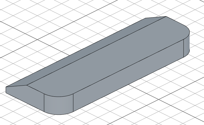
Extrude the bracket, fillet two side edges to round them, and add an angled chamfer to the end edges. chamfer(8, 90 - 25, true, ...) uses a distance of 8mm and an angle of 65° — the third argument true means the second parameter is an angle rather than a second distance. The edge().onPlane('yz', 31.5) filter narrows endEdges() to the edges lying on the plane parallel to yz at x = 31.5mm, so only those edges get chamfered.
const e1 = extrude(supportThickness);

fillet(12, e1.sideEdges(2, 3));

chamfer(8, 90 - 25, true, e1.endEdges(edge().onPlane('yz', 31.5)))
Step 2: Main Housing Body
Lower body
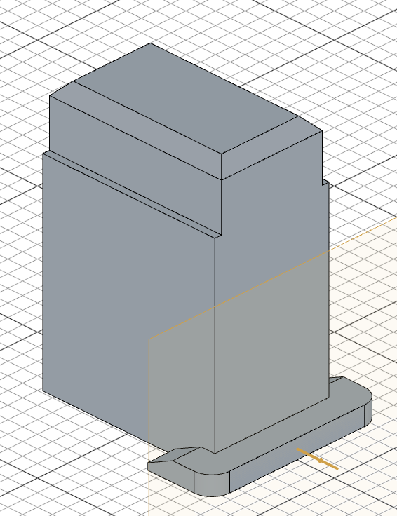
Sketch a 116 × 77 rectangle centered on the origin of the "top" plane and extrude it 130mm upward to form the main housing block. The pattern is the same as step 1 — four lines, coincident corners, horizontal/vertical constraints, a fixed corner, and two dimensions. Also create a reference plane on the bracket's side face — you'll use rightPlane later for the slot and bolt hole.
sketch("top", () => {
    const sg1 = line([-58, -38.5], [58, -38.5]);
    const sg2 = line([58, -38.5], [58, 38.5]);
    const sg3 = line([58, 38.5], [-58, 38.5]);
    const sg4 = line([-58, 38.5], [-58, -38.5]);
    coincident(sg1.end(), sg2.start());
    coincident(sg2.end(), sg3.start());
    coincident(sg3.end(), sg4.start());
    coincident(sg4.end(), sg1.start());
    horizontal(sg1);
    vertical(sg2);
    horizontal(sg3);
    vertical(sg4);
    fix(sg1.start(), [-58, -38.5]);
    distance(sg1.start(), sg1.end(), 116);
    distance(sg2.start(), sg2.end(), 77);
  });

const e2 = extrude(130);
const rightPlane = plane(e1.sideFaces(2))
Upper section
Sketch a slightly narrower rectangle on the end face of the lower body and extrude it 38mm more. The width change from 77mm to 68mm creates a stepped profile. Chamfer the top edges to finish.
sketch(e2.endFaces(), () => {
    const sg5 = line([-58, -34], [58, -34]);
    const sg6 = line([58, -34], [58, 34]);
    const sg7 = line([58, 34], [-58, 34]);
    const sg8 = line([-58, 34], [-58, -34]);
    coincident(sg5.end(), sg6.start());
    coincident(sg6.end(), sg7.start());
    coincident(sg7.end(), sg8.start());
    coincident(sg8.end(), sg5.start());
    horizontal(sg5);
    vertical(sg6);
    horizontal(sg7);
    vertical(sg8);
    fix(sg5.start(), [-58, -34]);
    distance(sg5.start(), sg5.end(), 116);
    distance(sg6.start(), sg6.end(), 68);
  });

const e3 = extrude(168 - 130);

chamfer(8, e3.endEdges());
Step 3: Internal Cavity
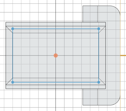
Sketch a centered 100 × 62 rectangle on the "xy" plane and cut downward 158mm with a 3° draft angle. The negative depth cuts downward, and .draft(-3) tapers the cavity walls inward — typical for cast parts where draft helps with mold release.
const p1 = plane("xy");
sketch(p1, () => {
    const sg9 = line([-50, -31], [50, -31]);
    const sg10 = line([50, -31], [50, 31]);
    const sg11 = line([50, 31], [-50, 31]);
    const sg12 = line([-50, 31], [-50, -31]);
    coincident(sg9.end(), sg10.start());
    coincident(sg10.end(), sg11.start());
    coincident(sg11.end(), sg12.start());
    coincident(sg12.end(), sg9.start());
    horizontal(sg9);
    vertical(sg10);
    horizontal(sg11);
    vertical(sg12);
    fix(sg9.start(), [-50, -31]);
    distance(sg9.start(), sg9.end(), 100);
    distance(sg10.start(), sg10.end(), 62);
  });

cut(-158).draft(-3)
Step 4: Side Slot and Bolt Hole
Sketch the slot profile
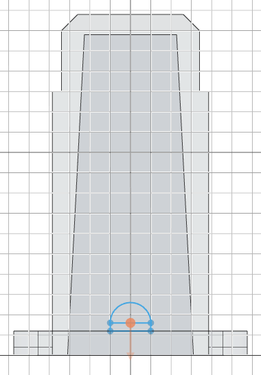
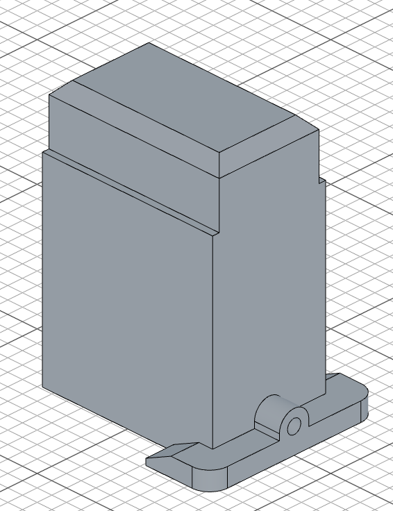
On rightPlane, build a keyhole-shaped profile: a narrow 20 × 4 rectangle whose top edge runs at y = 16, capped by a semicircular arc. The arc is declared with arc(start, end, center) — start and end sit on the top corners of the rectangle, and the center is the middle of the top edge, so it bulges upward. coincident() ties the arc's ends to the rectangle, and radius(cap, 10) dimensions it.
sketch(rightPlane, () => {
    const b = line([-10, 12], [10, 12]);
    const r = line([10, 12], [10, 16]);
    const t = line([10, 16], [-10, 16]);
    const l = line([-10, 16], [-10, 12]);
    const cap = arc([10, 16], [-10, 16], [0, 16]);
    coincident(b.end(), r.start());
    coincident(r.end(), t.start());
    coincident(t.end(), l.start());
    coincident(l.end(), b.start());
    coincident(cap.start(), t.start());
    coincident(cap.end(), t.end());
    horizontal(b);
    vertical(r);
    horizontal(t);
    vertical(l);
    radius(cap, 10);
    fix(b.start(), [-10, 12]);
    distance(b.start(), b.end(), 20);
    distance(r.start(), r.end(), 4);
});
Extrude the slot and cut the bolt hole
Extrude the slot profile 20mm inward, then sketch a circle on the same plane and cut through for the bolt hole. circle([0, 16], 9) places a 9mm-diameter circle at the arc's center.
extrude(-40 / 2)
sketch(rightPlane, () => {
    circle([0, 16], 9);
  });

cut();
Step 5: Side Bosses
Sketch the boss profile
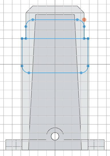
On the side face of the upper section, sketch a profile made of two stacked openings with selectively rounded corners. Each rounded corner is an explicit arc() joined to its neighboring lines with coincident() and tangent() constraints — the lower opening rounds its bottom corners, the upper slot rounds its top corners, creating a smooth transition. radius() dimensions one arc of each pair and equal() keeps its twin matched.
sketch(e2.sideFaces(0), () => {
    // Upper opening: 77 wide, y = 90..130, bottom corners rounded r = 8
    const b1 = line([-30.5, 90], [30.5, 90]);
    const br = arc([30.5, 90], [38.5, 98], [30.5, 98]);
    const r1 = line([38.5, 98], [38.5, 130]);
    const t1 = line([38.5, 130], [-38.5, 130]);
    const l1 = line([-38.5, 130], [-38.5, 98]);
    const bl = arc([-38.5, 98], [-30.5, 90], [-30.5, 98]);
    // Lower slot: 68 wide, y = 130..152, top corners rounded r = 8
    const b2 = line([-34, 130], [34, 130]);
    const r2 = line([34, 130], [34, 144]);
    const tr = arc([34, 144], [26, 152], [26, 144]);
    const t2 = line([26, 152], [-26, 152]);
    const tl = arc([-26, 152], [-34, 144], [-26, 144]);
    const l2 = line([-34, 144], [-34, 130]);
    coincident(b1.end(), br.start());
    coincident(br.end(), r1.start());
    coincident(r1.end(), t1.start());
    coincident(t1.end(), l1.start());
    coincident(l1.end(), bl.start());
    coincident(bl.end(), b1.start());
    coincident(b2.end(), r2.start());
    coincident(r2.end(), tr.start());
    coincident(tr.end(), t2.start());
    coincident(t2.end(), tl.start());
    coincident(tl.end(), l2.start());
    coincident(l2.end(), b2.start());
    horizontal(b1);
    vertical(r1);
    horizontal(t1);
    vertical(l1);
    horizontal(b2);
    vertical(r2);
    horizontal(t2);
    vertical(l2);
    tangent(b1, br);
    tangent(br, r1);
    tangent(l1, bl);
    tangent(bl, b1);
    tangent(r2, tr);
    tangent(tr, t2);
    tangent(t2, tl);
    tangent(tl, l2);
    radius(br, 8);
    equal(br, bl);
    radius(tr, 8);
    equal(tr, tl);
    fix(t1.start(), [38.5, 130]);
    fix(b2.start(), [-34, 130]);
});
Extrude and mirror
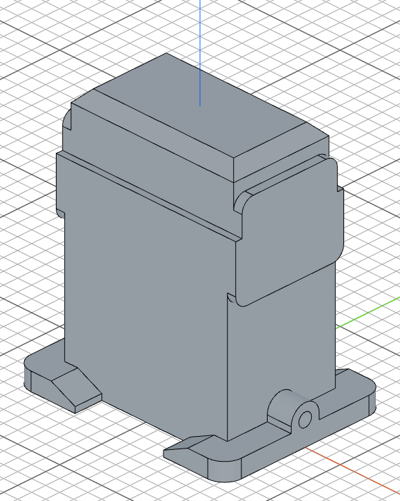
Extrude the boss by (128 - 116) / 2 = 6mm. .drill(false) prevents the extrusion from cutting into the existing body. Then mirror("yz") creates the matching boss on the opposite side.
const e5 = extrude((128 - 116)/2).drill(false)
mirror("yz")
Step 6: Bearing Bore and Counterbore
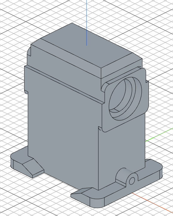
Cut a through-hole for the bearing with a 42mm-diameter circle at [0, 122], then add a larger 54mm-diameter counterbore 10mm deep. repeat("mirror", "yz", counterbore) mirrors the counterbore to the opposite side.
sketch(e5.endFaces(), () => {
    circle([0, 122], 42);
  });

cut()

sketch(e5.endFaces(), () => {
    circle([0, 122], 54);
  });

const counterbore = cut(10);
repeat("mirror", "yz", counterbore);
Step 7: Front Plate and Mounting Holes
Circular front plate
Sketch a large circle on the front face of the housing and extrude it 5.5mm to create the bearing mounting plate. The plate is centered on the face — [0, 65] in face coordinates, halfway up the 130mm housing body.
sketch(e2.sideFaces(3), () => {
    circle([0, 65], 122);
  });

const e6 = extrude(11/2)
Keyway notches
Cut a narrow 5 × 40 rectangular notch at the side of the plate, vertically centered on the plate's y = 65 centerline. repeat("mirror", "yz", c2) mirrors the notch to the other side.
sketch(e6.endFaces(), () => {
    const sg17 = line([58, 45], [63, 45]);
    const sg18 = line([63, 45], [63, 85]);
    const sg19 = line([63, 85], [58, 85]);
    const sg20 = line([58, 85], [58, 45]);
    coincident(sg17.end(), sg18.start());
    coincident(sg18.end(), sg19.start());
    coincident(sg19.end(), sg20.start());
    coincident(sg20.end(), sg17.start());
    horizontal(sg17);
    vertical(sg18);
    horizontal(sg19);
    vertical(sg20);
    fix(sg17.start(), [58, 45]);
    distance(sg17.start(), sg17.end(), 5);
    distance(sg18.start(), sg18.end(), 40);
  });

const c2 = cut()
repeat("mirror", "yz", c2);
Bolt hole pattern
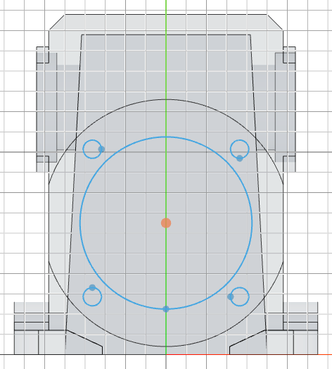
Place a 9mm-diameter bolt hole on the ⌀103 bolt circle around the plate center [0, 65] — its center sits 103 / 2 out at 45°, i.e. [103 / 2 / Math.SQRT2, 65 + 103 / 2 / Math.SQRT2]. copy('circular', [0, 65], ..., c1) repeats the hole 4 times around the plate center at equal 90° intervals, and circle([0, 65], 85) adds the large central bore.
sketch(e6.endFaces(), () => {
    const c1 = circle([103 / 2 / Math.SQRT2, 65 + 103 / 2 / Math.SQRT2], 9);
    circle([0, 65], 85);
    copy('circular', [0, 65], {
        count: 4,
        angle: 360
    }, c1);
});

cut()
Final mirror
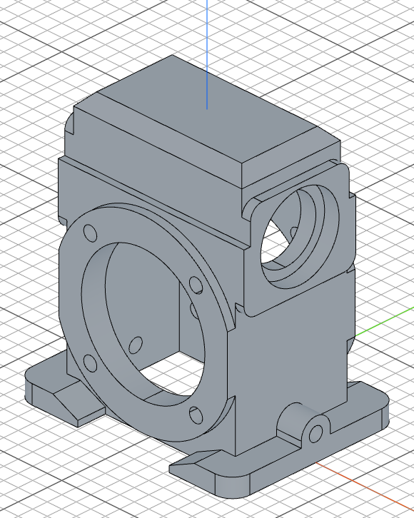
mirror("front") mirrors the entire model across the front plane to complete the symmetric gear housing.
mirror("front")
Full code
Open this model in the 3D viewerimport { arc, chamfer, circle, copy, cut, extrude, fillet, line, mirror, plane, repeat, sketch } from "fluidcad/core";
import { edge } from "fluidcad/filters";
import { coincident, distance, equal, fix, horizontal, radius, tangent, vertical } from "fluidcad/constraints";
let supportWidth = (150 - 63) / 2;
let supportThickness = 12;
sketch("xy", () => {
const b = line([63 / 2, -115 / 2], [63 / 2 + supportWidth, -115 / 2]);
const r = line([63 / 2 + supportWidth, -115 / 2], [63 / 2 + supportWidth, 115 / 2]);
const t = line([63 / 2 + supportWidth, 115 / 2], [63 / 2, 115 / 2]);
const l = line([63 / 2, 115 / 2], [63 / 2, -115 / 2]);
coincident(b.end(), r.start());
coincident(r.end(), t.start());
coincident(t.end(), l.start());
coincident(l.end(), b.start());
horizontal(b);
vertical(r);
horizontal(t);
vertical(l);
fix(b.start(), [63 / 2, -115 / 2]);
distance(b.start(), b.end(), supportWidth);
distance(r.start(), r.end(), 115);
});
const e1 = extrude(supportThickness);
fillet(12, e1.sideEdges(2, 3));
chamfer(8, 90 - 25, true, e1.endEdges(edge().onPlane('yz', 31.5)))
sketch("top", () => {
const sg1 = line([-58, -38.5], [58, -38.5]);
const sg2 = line([58, -38.5], [58, 38.5]);
const sg3 = line([58, 38.5], [-58, 38.5]);
const sg4 = line([-58, 38.5], [-58, -38.5]);
coincident(sg1.end(), sg2.start());
coincident(sg2.end(), sg3.start());
coincident(sg3.end(), sg4.start());
coincident(sg4.end(), sg1.start());
horizontal(sg1);
vertical(sg2);
horizontal(sg3);
vertical(sg4);
fix(sg1.start(), [-58, -38.5]);
distance(sg1.start(), sg1.end(), 116);
distance(sg2.start(), sg2.end(), 77);
});
const e2 = extrude(130);
const rightPlane = plane(e1.sideFaces(2))
sketch(e2.endFaces(), () => {
const sg5 = line([-58, -34], [58, -34]);
const sg6 = line([58, -34], [58, 34]);
const sg7 = line([58, 34], [-58, 34]);
const sg8 = line([-58, 34], [-58, -34]);
coincident(sg5.end(), sg6.start());
coincident(sg6.end(), sg7.start());
coincident(sg7.end(), sg8.start());
coincident(sg8.end(), sg5.start());
horizontal(sg5);
vertical(sg6);
horizontal(sg7);
vertical(sg8);
fix(sg5.start(), [-58, -34]);
distance(sg5.start(), sg5.end(), 116);
distance(sg6.start(), sg6.end(), 68);
});
const e3 = extrude(168 - 130);
chamfer(8, e3.endEdges());
const p1 = plane("xy");
sketch(p1, () => {
const sg9 = line([-50, -31], [50, -31]);
const sg10 = line([50, -31], [50, 31]);
const sg11 = line([50, 31], [-50, 31]);
const sg12 = line([-50, 31], [-50, -31]);
coincident(sg9.end(), sg10.start());
coincident(sg10.end(), sg11.start());
coincident(sg11.end(), sg12.start());
coincident(sg12.end(), sg9.start());
horizontal(sg9);
vertical(sg10);
horizontal(sg11);
vertical(sg12);
fix(sg9.start(), [-50, -31]);
distance(sg9.start(), sg9.end(), 100);
distance(sg10.start(), sg10.end(), 62);
});
cut(-158).draft(-3)
sketch(rightPlane, () => {
const b = line([-10, 12], [10, 12]);
const r = line([10, 12], [10, 16]);
const t = line([10, 16], [-10, 16]);
const l = line([-10, 16], [-10, 12]);
const cap = arc([10, 16], [-10, 16], [0, 16]);
coincident(b.end(), r.start());
coincident(r.end(), t.start());
coincident(t.end(), l.start());
coincident(l.end(), b.start());
coincident(cap.start(), t.start());
coincident(cap.end(), t.end());
horizontal(b);
vertical(r);
horizontal(t);
vertical(l);
radius(cap, 10);
fix(b.start(), [-10, 12]);
distance(b.start(), b.end(), 20);
distance(r.start(), r.end(), 4);
});
extrude(-40 / 2)
sketch(rightPlane, () => {
circle([0, 16], 9);
});
cut();
sketch(e2.sideFaces(0), () => {
// Upper opening: 77 wide, y = 90..130, bottom corners rounded r = 8
const b1 = line([-30.5, 90], [30.5, 90]);
const br = arc([30.5, 90], [38.5, 98], [30.5, 98]);
const r1 = line([38.5, 98], [38.5, 130]);
const t1 = line([38.5, 130], [-38.5, 130]);
const l1 = line([-38.5, 130], [-38.5, 98]);
const bl = arc([-38.5, 98], [-30.5, 90], [-30.5, 98]);
// Lower slot: 68 wide, y = 130..152, top corners rounded r = 8
const b2 = line([-34, 130], [34, 130]);
const r2 = line([34, 130], [34, 144]);
const tr = arc([34, 144], [26, 152], [26, 144]);
const t2 = line([26, 152], [-26, 152]);
const tl = arc([-26, 152], [-34, 144], [-26, 144]);
const l2 = line([-34, 144], [-34, 130]);
coincident(b1.end(), br.start());
coincident(br.end(), r1.start());
coincident(r1.end(), t1.start());
coincident(t1.end(), l1.start());
coincident(l1.end(), bl.start());
coincident(bl.end(), b1.start());
coincident(b2.end(), r2.start());
coincident(r2.end(), tr.start());
coincident(tr.end(), t2.start());
coincident(t2.end(), tl.start());
coincident(tl.end(), l2.start());
coincident(l2.end(), b2.start());
horizontal(b1);
vertical(r1);
horizontal(t1);
vertical(l1);
horizontal(b2);
vertical(r2);
horizontal(t2);
vertical(l2);
tangent(b1, br);
tangent(br, r1);
tangent(l1, bl);
tangent(bl, b1);
tangent(r2, tr);
tangent(tr, t2);
tangent(t2, tl);
tangent(tl, l2);
radius(br, 8);
equal(br, bl);
radius(tr, 8);
equal(tr, tl);
fix(t1.start(), [38.5, 130]);
fix(b2.start(), [-34, 130]);
});
const e5 = extrude((128 - 116)/2).drill(false)
mirror("yz")
sketch(e5.endFaces(), () => {
circle([0, 122], 42);
});
cut()
sketch(e5.endFaces(), () => {
circle([0, 122], 54);
});
const counterbore = cut(10);
repeat("mirror", "yz", counterbore);
sketch(e2.sideFaces(3), () => {
circle([0, 65], 122);
});
const e6 = extrude(11/2)
sketch(e6.endFaces(), () => {
const sg17 = line([58, 45], [63, 45]);
const sg18 = line([63, 45], [63, 85]);
const sg19 = line([63, 85], [58, 85]);
const sg20 = line([58, 85], [58, 45]);
coincident(sg17.end(), sg18.start());
coincident(sg18.end(), sg19.start());
coincident(sg19.end(), sg20.start());
coincident(sg20.end(), sg17.start());
horizontal(sg17);
vertical(sg18);
horizontal(sg19);
vertical(sg20);
fix(sg17.start(), [58, 45]);
distance(sg17.start(), sg17.end(), 5);
distance(sg18.start(), sg18.end(), 40);
});
const c2 = cut()
repeat("mirror", "yz", c2);
sketch(e6.endFaces(), () => {
const c1 = circle([103 / 2 / Math.SQRT2, 65 + 103 / 2 / Math.SQRT2], 9);
circle([0, 65], 85);
copy('circular', [0, 65], {
count: 4,
angle: 360
}, c1);
});
cut()
mirror("front")
What you practiced
- Constraint sketches —
sketch(plane, callback): geometry guesses pinned down bycoincident,horizontal/vertical,fix, anddistanceconstraints arc(start, end, center)— declares an arc by its endpoints and center;radius()dimensions ittangent()+equal()— smooth rounded corners built from explicit arcs kept equal in radiusfillet()— rounds selected edges with a given radiuschamfer()with angle — creates chamfers using a distance and angle whenisAngleistrueedge().onPlane()— filters an edge selection down to the edges lying on a specific planeplane()— creates a reference plane from an existing face for subsequent sketchescut().draft()— cuts material with tapered walls for mold-release draft angles.drill(false)— extrudes material without cutting into the existing bodymirror()— mirrors geometry across a principal planerepeat("mirror", ...)— mirrors specific operations to the opposite sidecopy('circular', ...)— creates circular patterns of sketch elements