Building a Grooved Box
In this tutorial, you'll build a grooved storage box based on the original design by Too Tall Toby. You build it from the FluidCAD workspace: a centered rounded rectangle, an open shell with a smooth interior, and two crossing patterns of shallow grooves. The full code at the end is the code produced by the tools, with tidier names.
Before you start
Open a workspace and click + in the top bar to create grooved-box.fluid.js. Use millimeters for this tutorial. The screenshots use the light theme, available from the sun/moon button at the top right.
- Ctrl+click adds to a selection. A plain click normally replaces it; the Intersect dialog accumulates face picks and clicking a picked face removes it.
- Right-click a face to select a named group or its tangent faces. Hover a menu item to preview the group.
- The DOF pill at the bottom of a sketch reads Fully constrained when nothing is left free to move.
- Each feature dialog shows the statement it will write. Apply or Enter commits it; Exit / Cancel or Escape discards it.
- Use Fit to view if the model is outside the viewport. Inside a sketch, N looks straight down its plane.
Step 1: The rounded base
Start on the XY plane
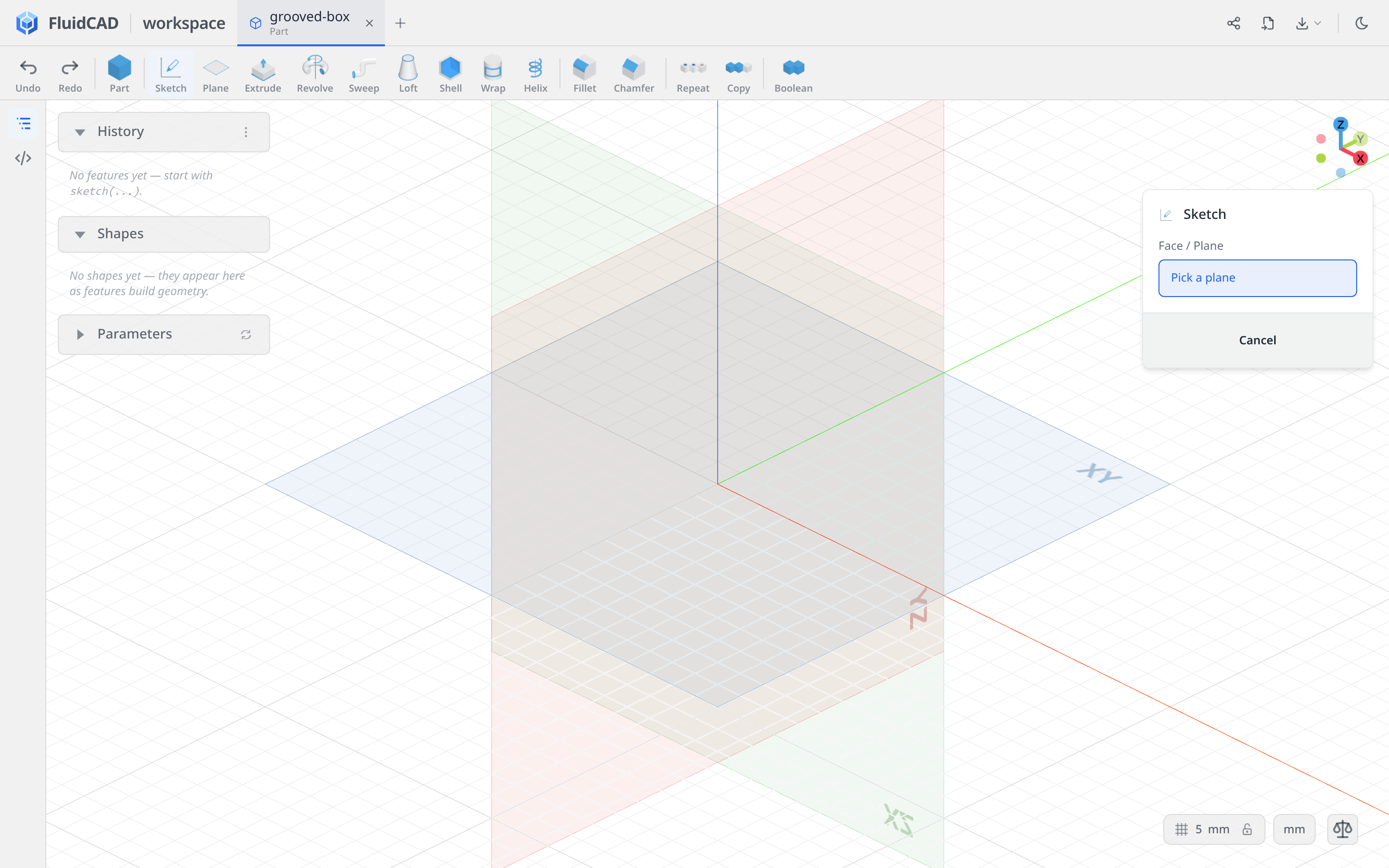
Click Sketch, then click the XY plane in the viewport.
Draw one centered, rounded rectangle
Pick Rectangle and enable both Rounded and Centered in its dropdown.
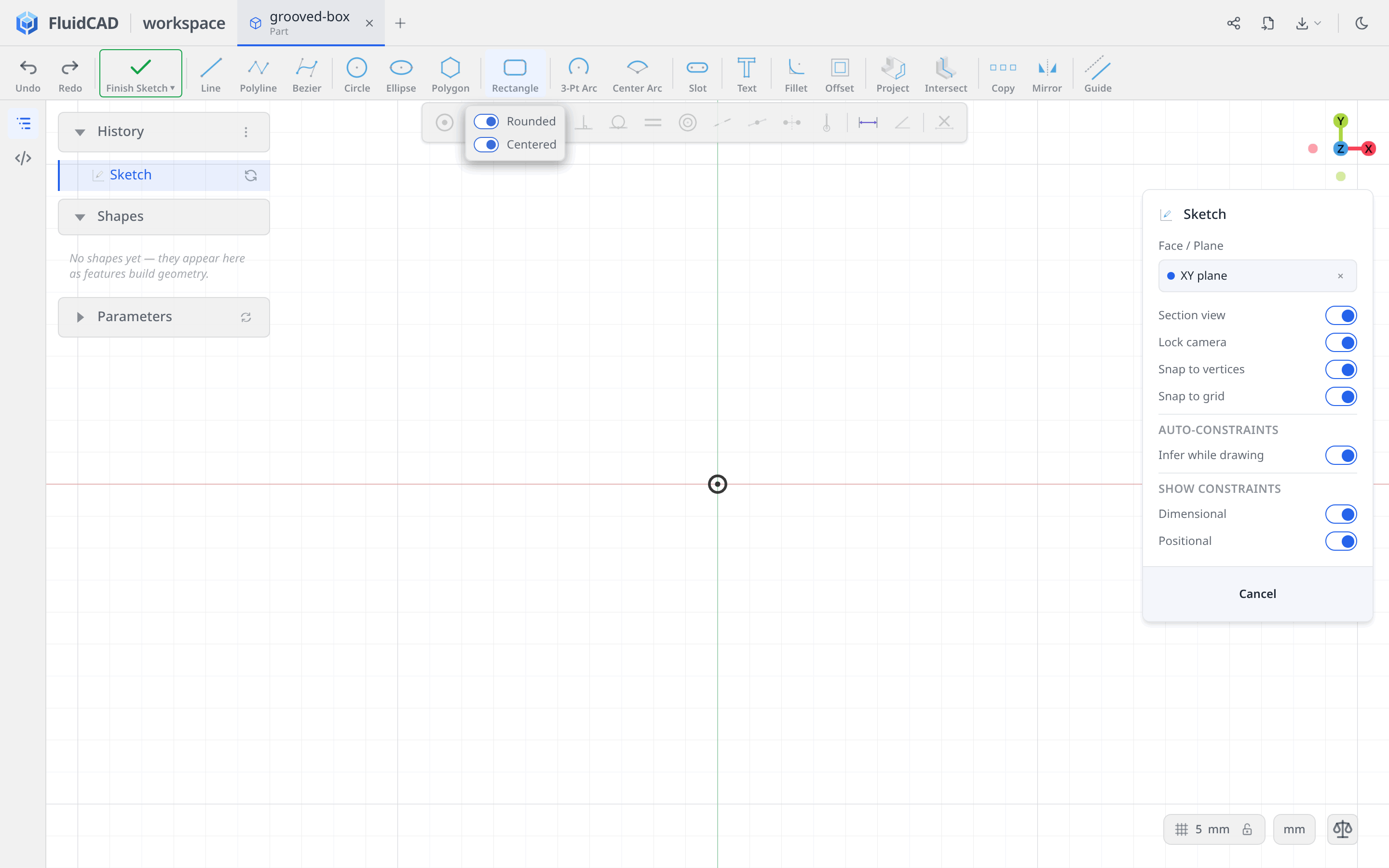
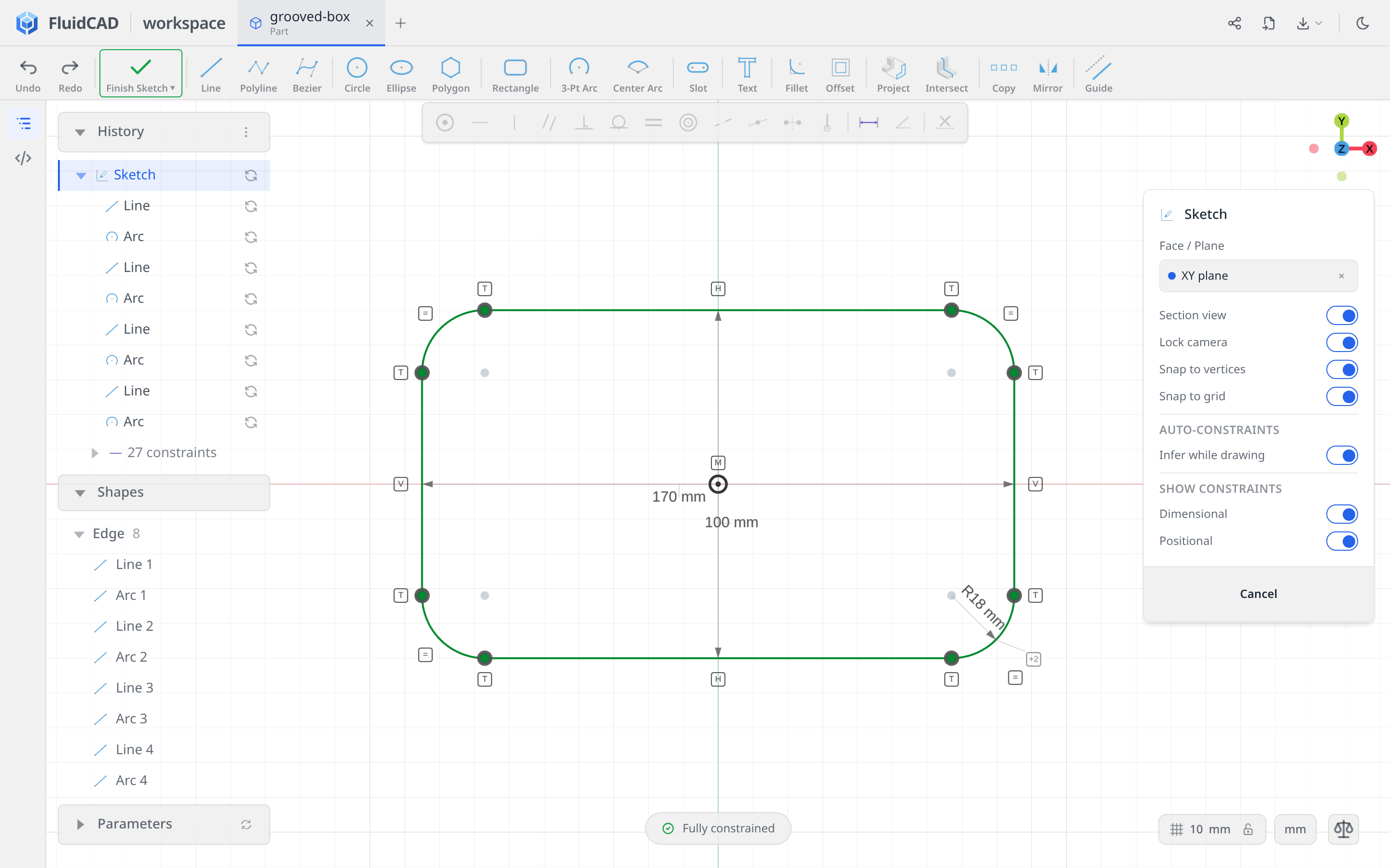
Click the origin for the center. Move the pointer up and to the right, type 170 for W, and press Enter. Type 100 for H, press Enter, then 18 for R and Enter. Press Escape to leave the drawing tool and fit the sketch to the view.
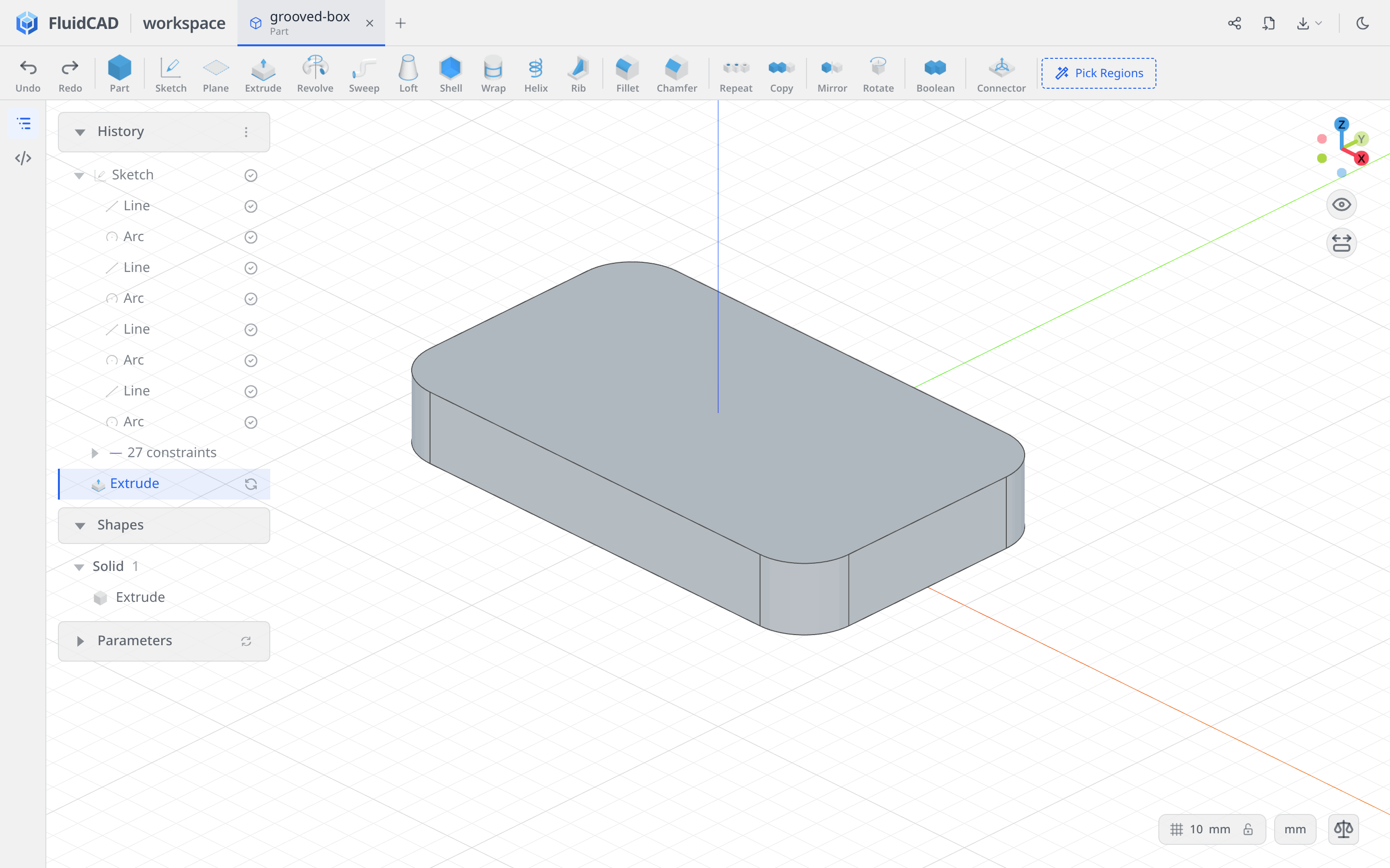
The dimensions describe the overall width and height, including the corners. The tool creates four straight sides and four tangent arcs, with equal radii. Clicking the origin in Centered mode anchors their center, so the pill reads Fully constrained without adding any more constraints.
Extrude the block
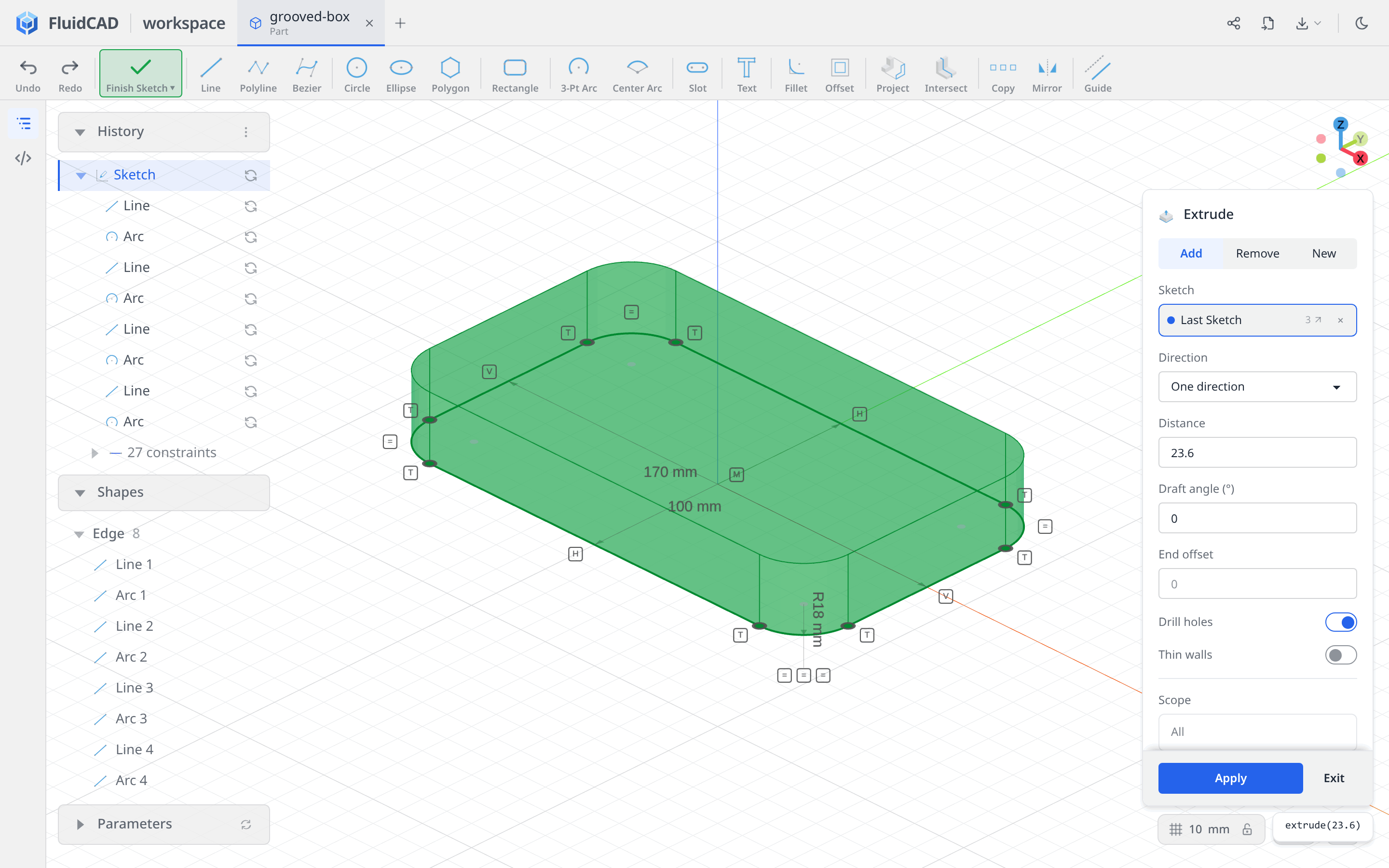
Click Extrude on the toolbar. Leave Add and One direction selected, and set Distance to 23.6. The green ghost shows the block and the statement reads extrude(23.6).
Click Apply.
Step 2: Hollow and round the interior
Remove the top face with Shell
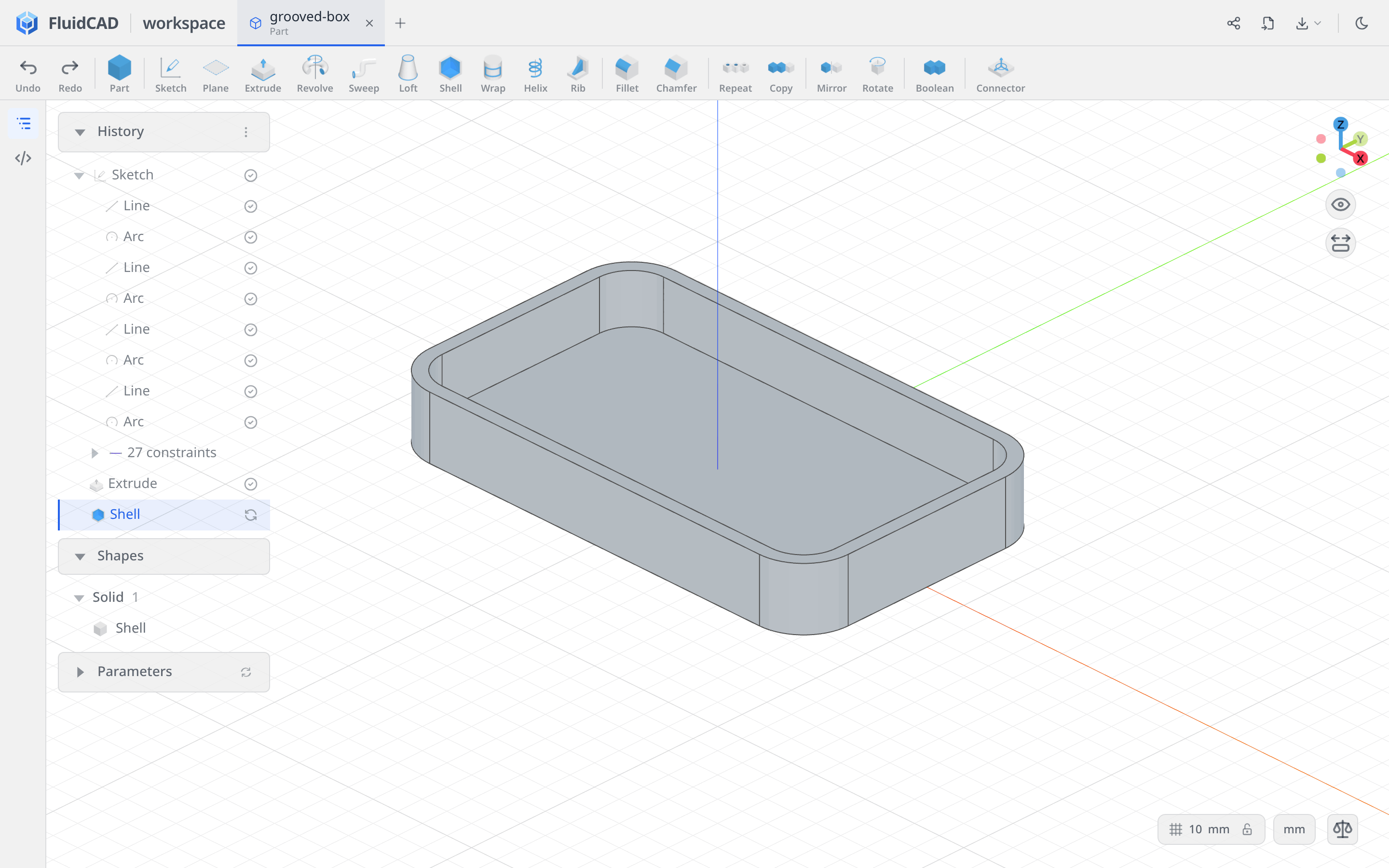
Click Shell, then click the block's top face. Set Thickness to -5 and leave Join type on Arc. Negative thickness offsets inward, preserving the outside dimensions and leaving 5 mm walls and a 5 mm bottom. The selected top face is the opening; the statement reads shell(-5, e.endFaces()).
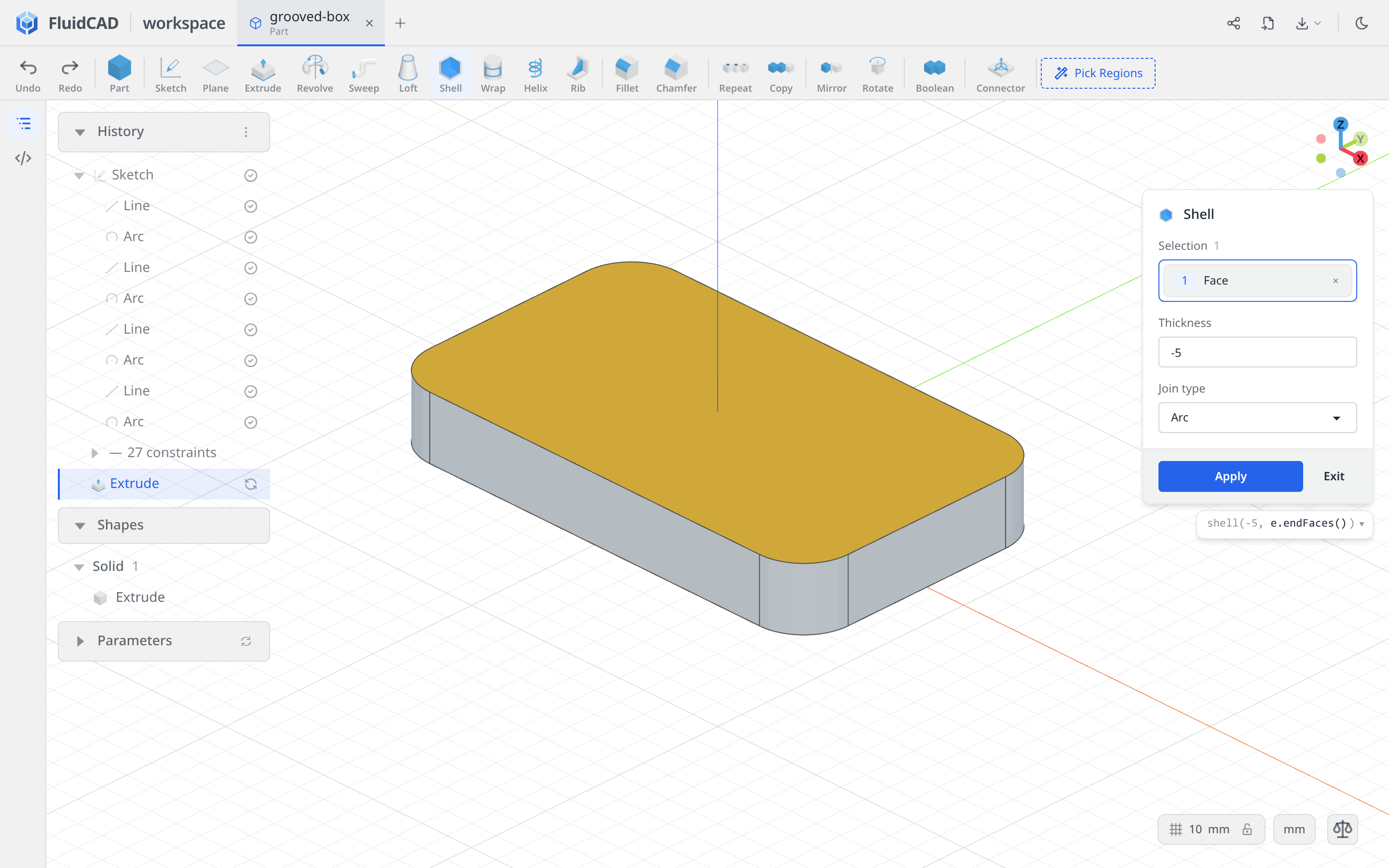
Click Apply.
Fillet the internal edges
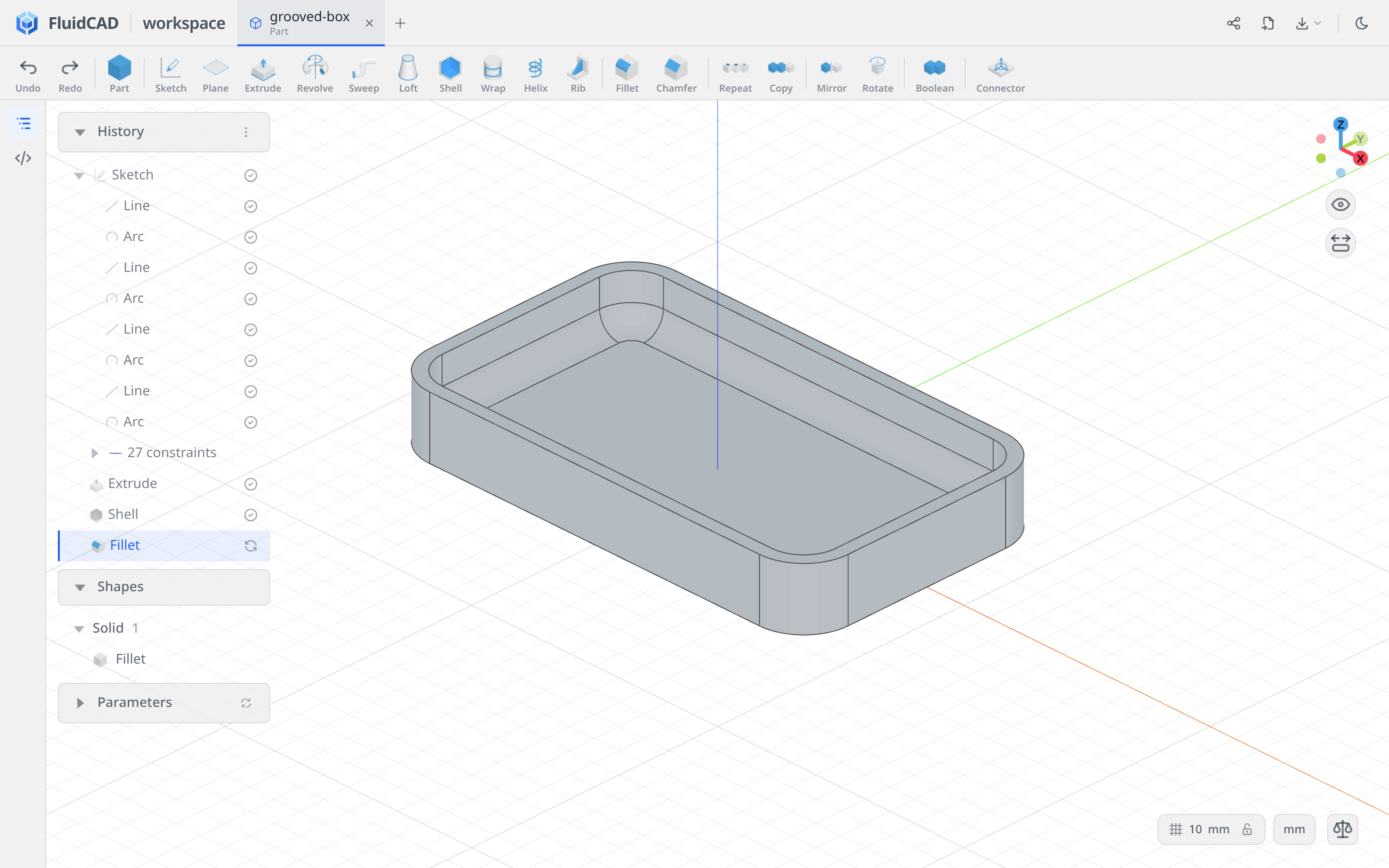
Click Fillet. Click an edge where the inside floor meets a wall, then double-click that edge to expand the selection to the shell's internal edges. The dialog lists 16 edges, including the tangent seams around the corners. Check that the outside edges and top rim are not selected.
Set Radius to 8. The statement reads fillet(8, sh.internalEdges()), and the green ghost shows the rounded transition from floor to wall.
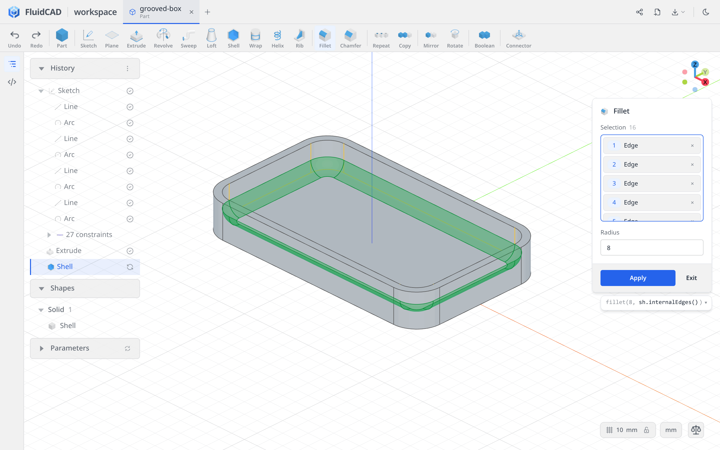
Click Apply.
Step 3: Capture both groove profiles
The grooves follow the outside walls, cross the rim, and run down the inside walls and across the floor. Intersect captures that cross-section directly from the box's faces.
Make both sketches before cutting either one. That keeps the second profile independent of the grooves made from the first.
Intersect on the YZ plane
Click Sketch and choose the YZ plane. In the Sketch panel, turn off Section view and Lock camera. Drag in the viewport to look down into the box: you need to see the floor, rim, and an outside wall to pick them.
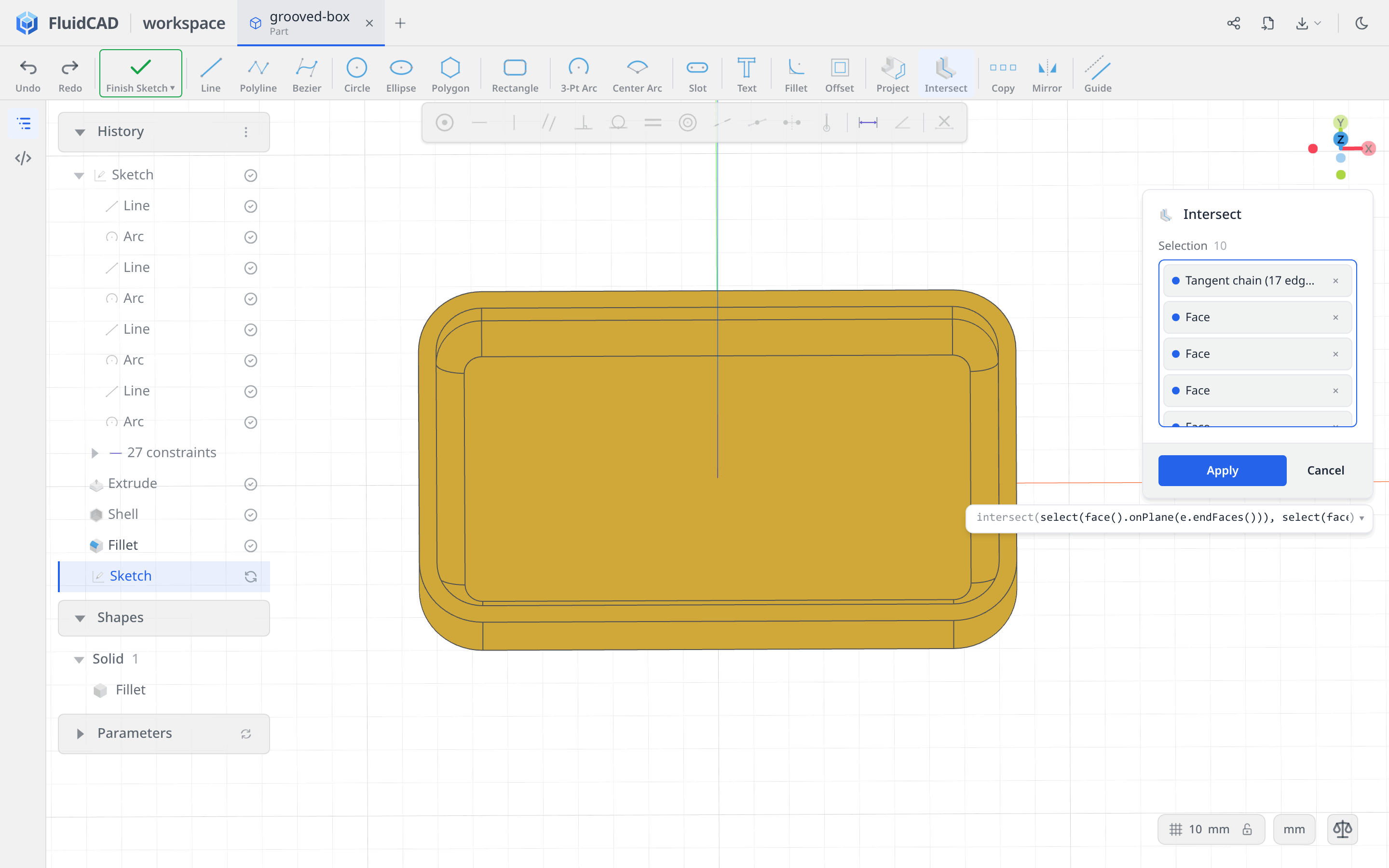
Click Intersect, then select these surfaces:
- Right-click the inside floor and choose Tangent Faces (17). This includes the floor, the rounded transitions, and the inside walls.
- Click the flat top rim to add it.
- Right-click an outside wall and choose Extrude Side Faces (8) to add the four straight walls and four rounded corners.
Leave out the flat underside. Including it would close the cross-section across the bottom; this groove needs an open profile following the other surfaces. The dialog shows 10 selection entries: one tangent group, the rim, and eight outside faces. Faces that do not cross the sketch plane contribute no curves.
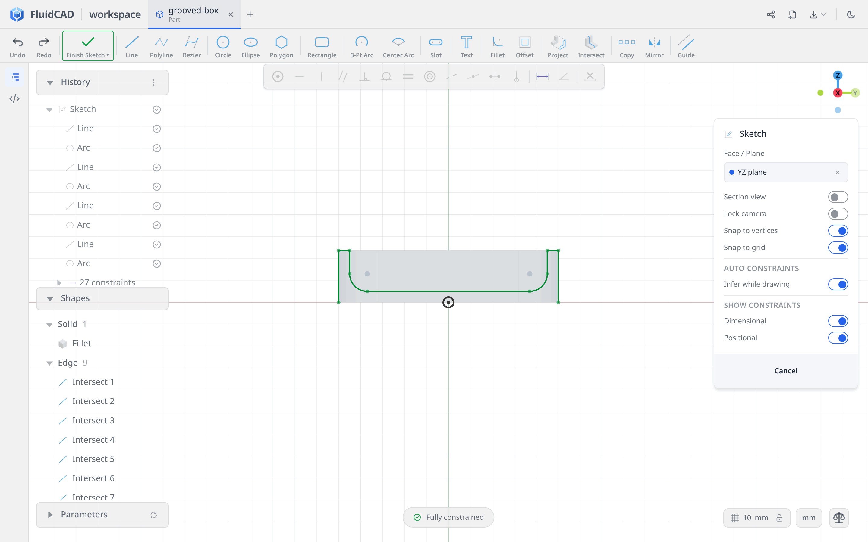
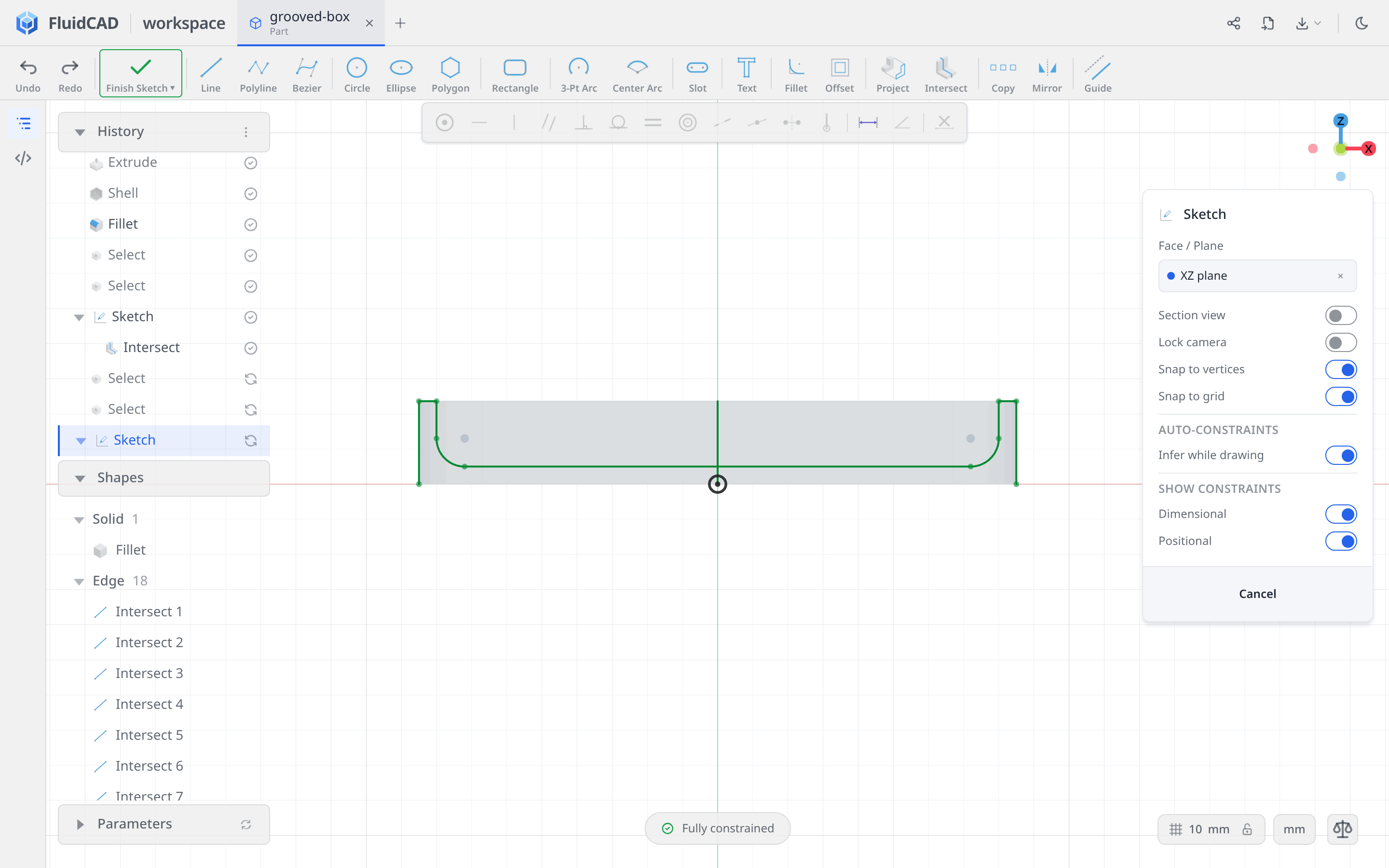
Click Apply, then press N. The intersection is fixed reference geometry, so it is already Fully constrained. Notice the two open ends at the underside and the rounded path across the inside floor.
Capture the XZ profile as well
Click Finish Sketch, then Sketch. Rotate the view if necessary to expose the XZ plane, then click it. Keep Section view and Lock camera off while picking.
Choose Intersect and repeat the same three selections: the floor's Tangent Faces (17), the top rim, and the outside wall's Extrude Side Faces (8).
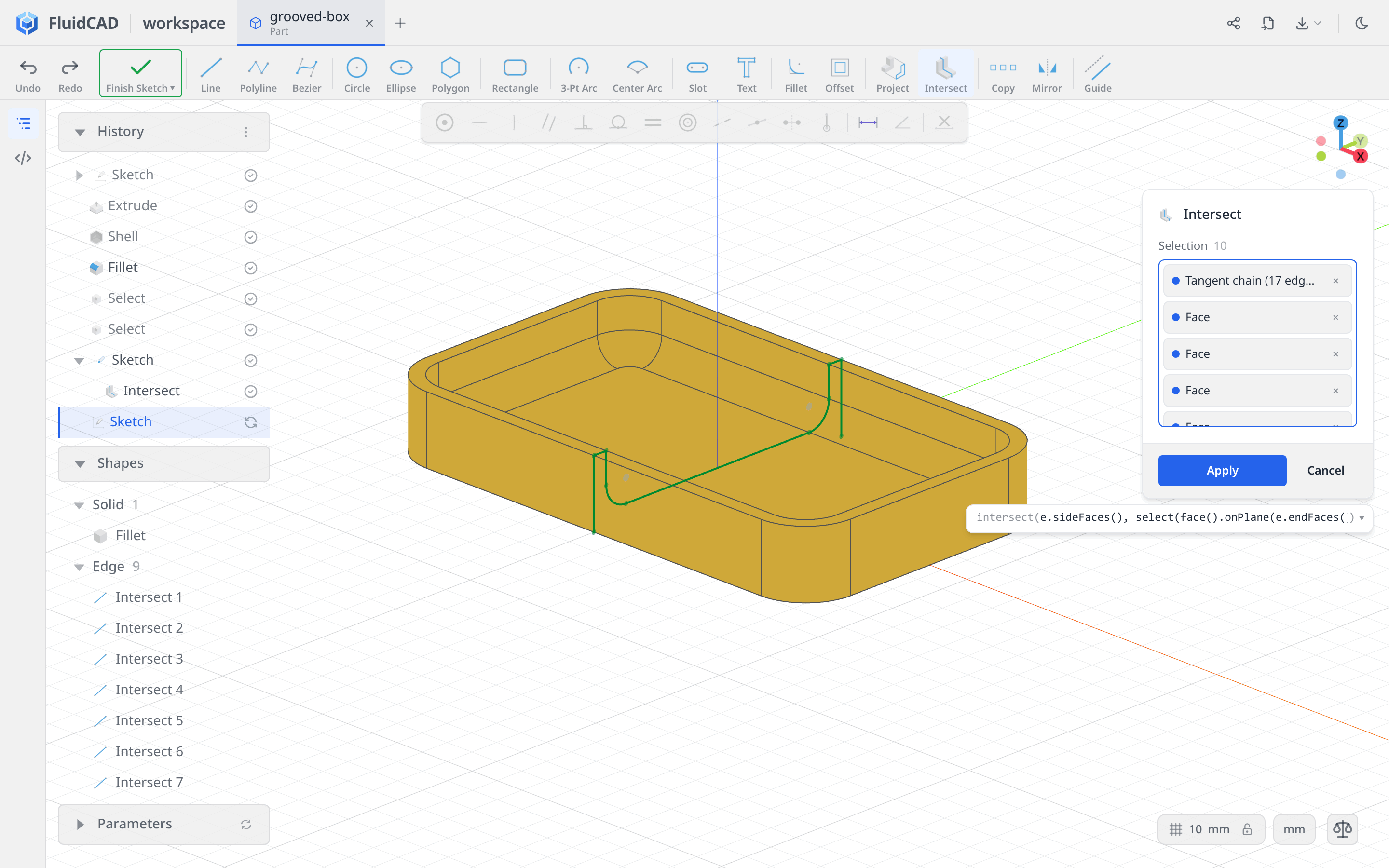
Click Apply and press N. This profile spans the longer, 170 mm dimension of the box. The earlier YZ sketch remains in History for the second set of grooves.
Step 4: Cut and repeat the first grooves
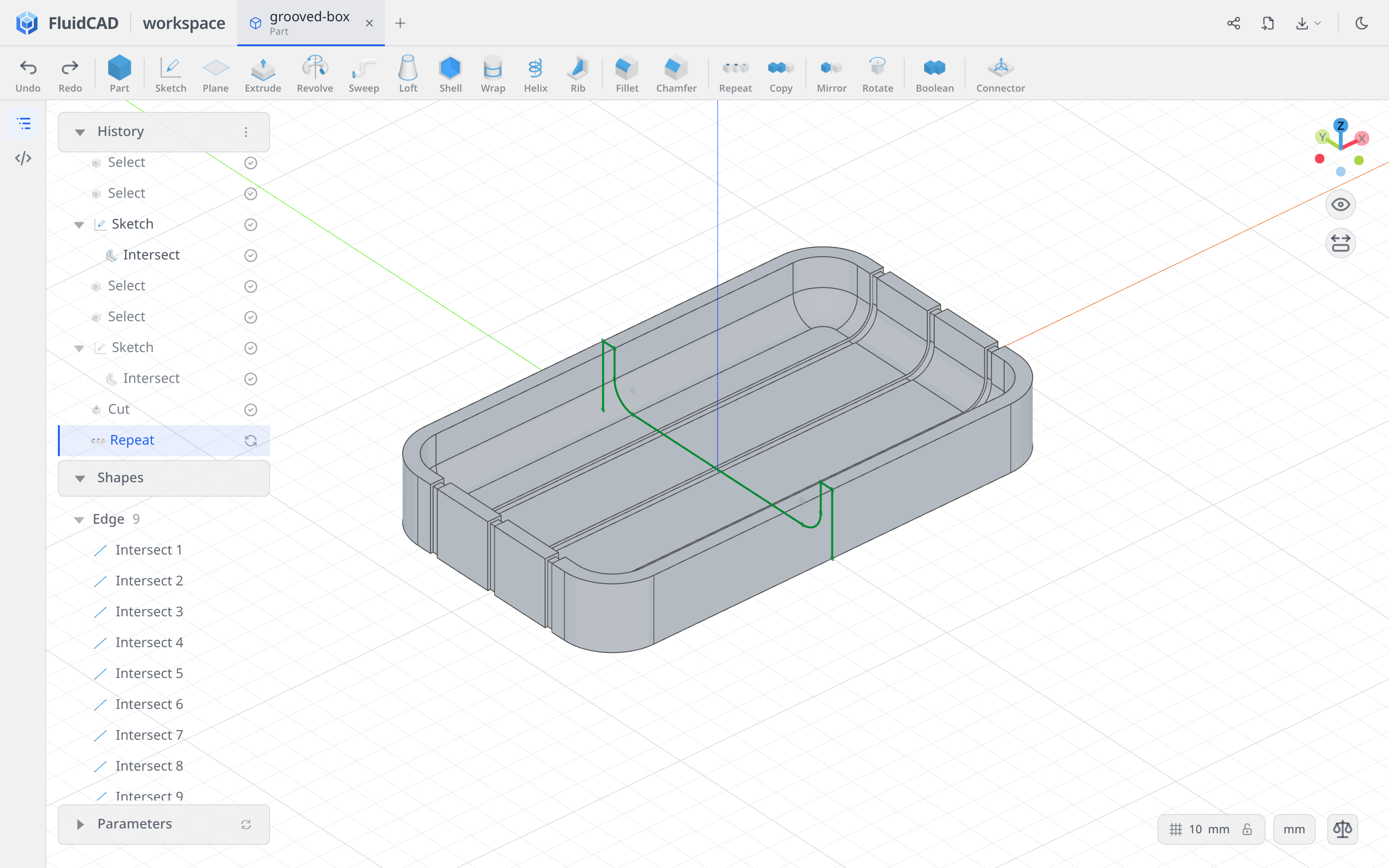
Make the thin symmetric cut
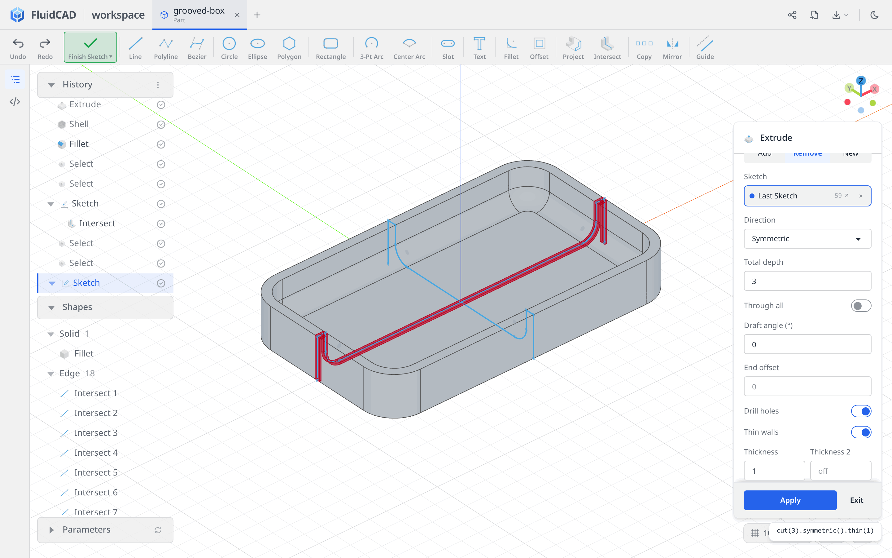
With the XZ sketch active, click Extrude on the toolbar. Select Remove, set Direction to Symmetric, and enter 3 for Total depth. Leave Through all off.
Enable Thin walls and set Thickness to 1; leave Thickness 2 off. Scroll within the dialog if the thickness field is below the visible area.
Drag in the viewport to orbit back to a view into the box. The 3 mm total depth is the groove's width, split 1.5 mm each side of the sketch plane. The 1 mm thickness makes a narrow strip following the profile into the material. Check the red preview: it should enter the floor and walls, not sit in the empty interior. The statement reads cut(3).symmetric().thin(1).
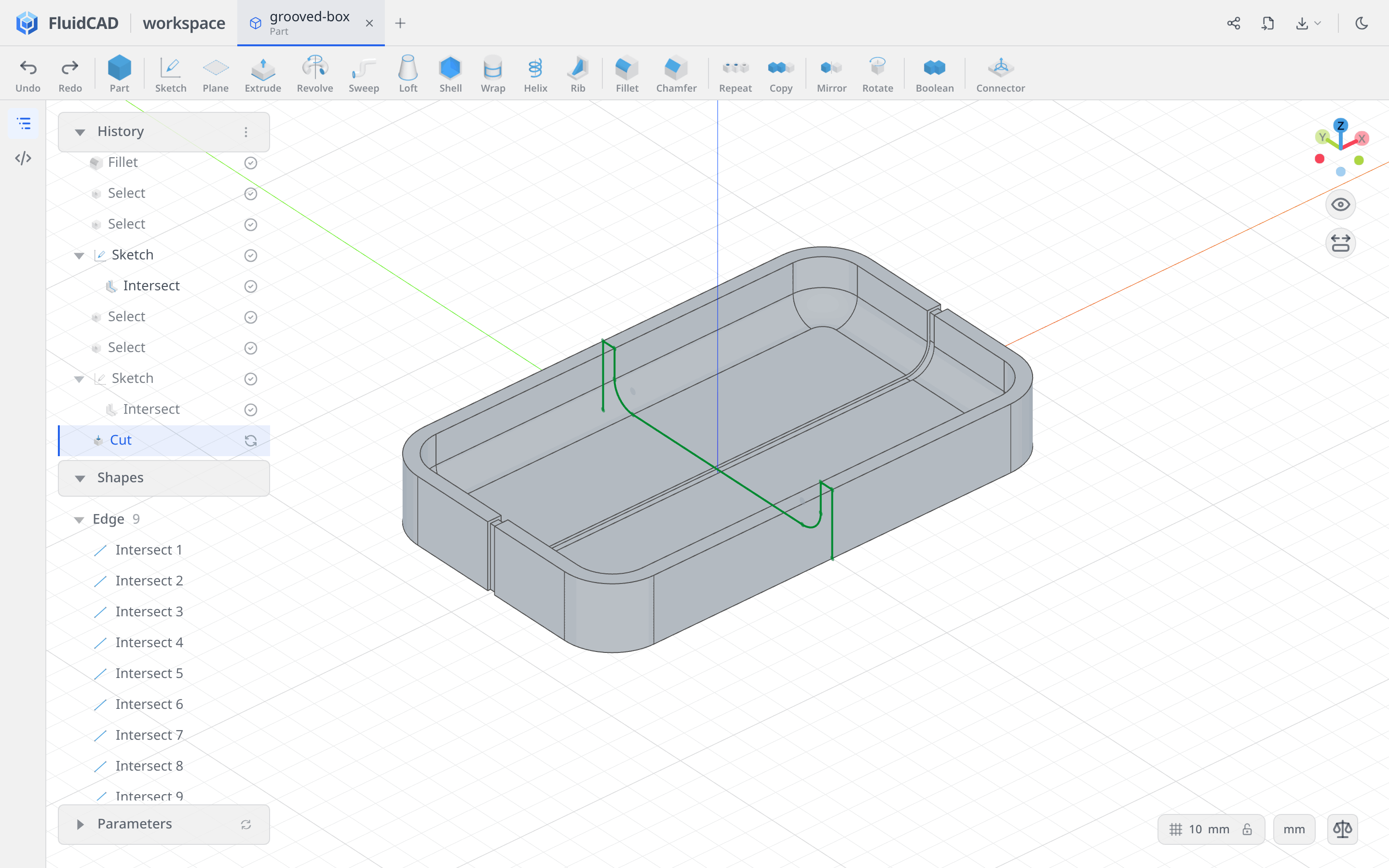
Click Apply.
Repeat along Y
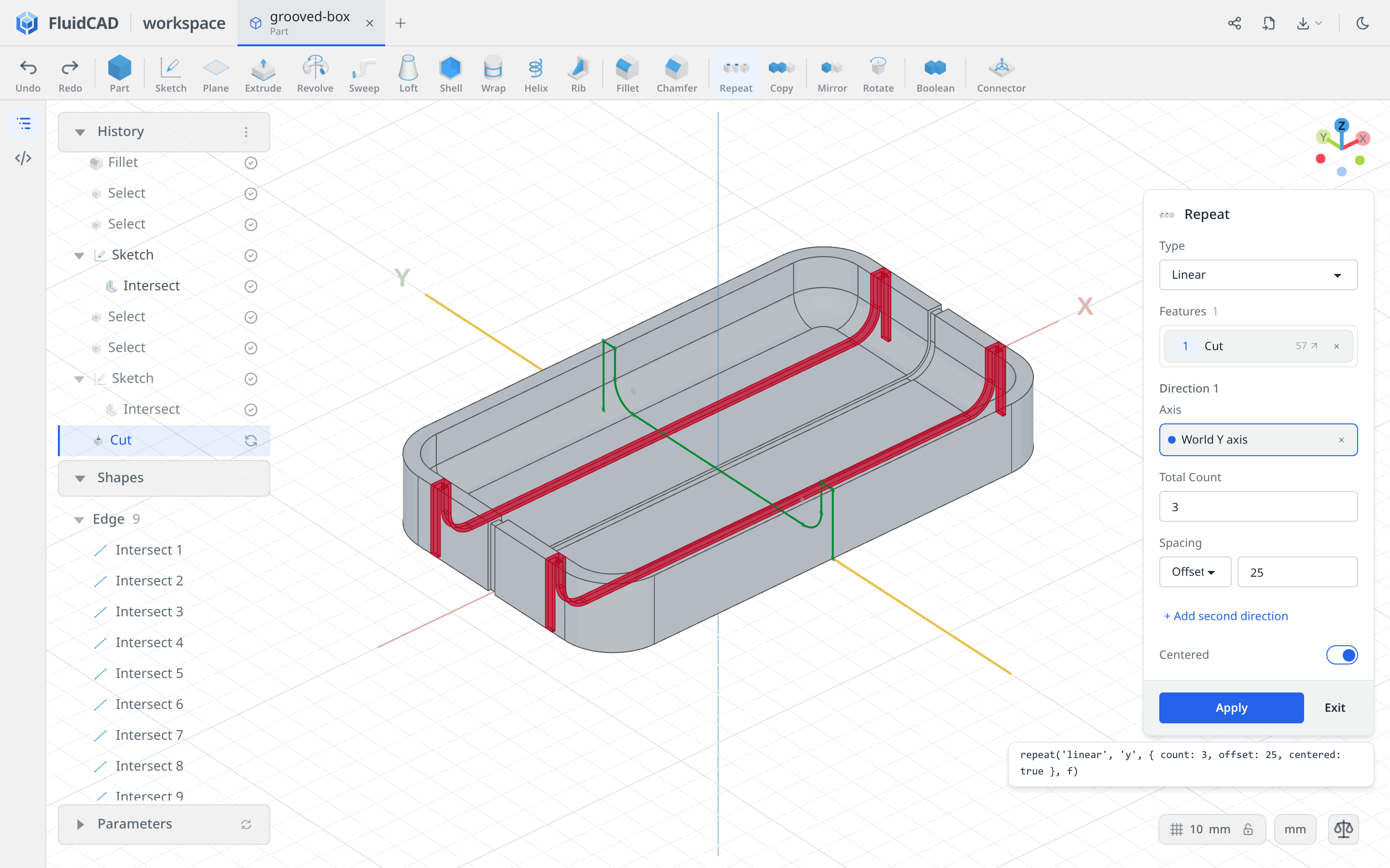
Click Repeat and leave Type on Linear. Click the new Cut row in History to add it to Features. Click the Axis slot, then the green Y axis in the viewport; the chip should read World Y axis.
Set Total Count to 3, Spacing to Offset with a value of 25, and enable Centered. The count includes the original groove, so the two red previews sit at Y = −25 and +25 around the existing cut at Y = 0.
Click Apply.
Step 5: Add the crossing grooves
Use the earlier YZ sketch
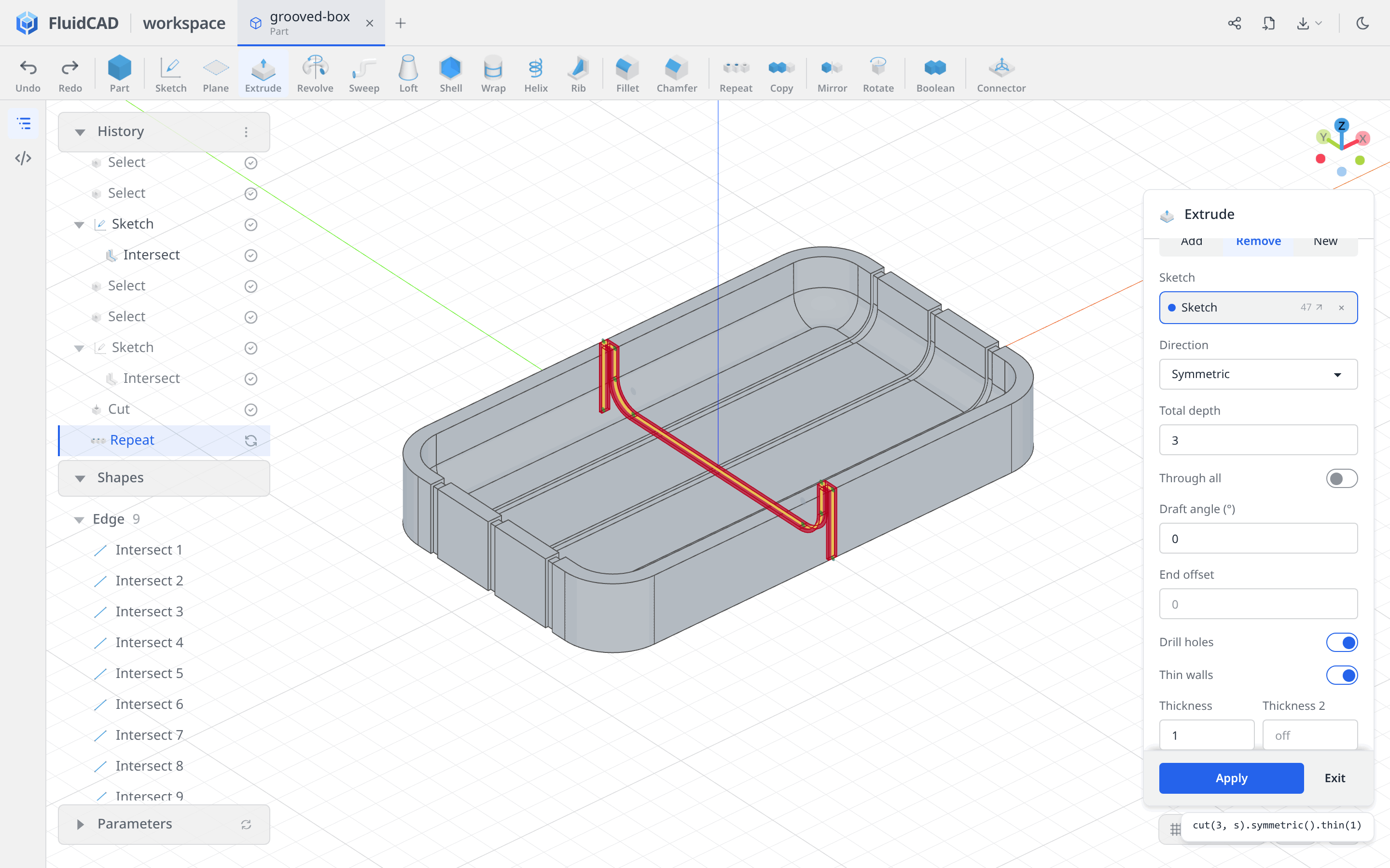
Click Extrude in the toolbar, then click the YZ Sketch row in History — the first intersection sketch, immediately after the interior fillet and its face selections. Do not create another intersection of the now-grooved box.
Select Remove, Symmetric, Total depth 3, and Thin walls with Thickness 1. Leave Thickness 2 off. The preview crosses the three existing grooves at right angles; its statement includes the earlier sketch reference, cut(3, s).symmetric().thin(1) (the generated name may differ).
Click Apply.
Repeat along X
Click Repeat, select the newest Cut row in History, and choose the red X axis through the Axis slot. Check that it reads World X axis.
Set Total Count to 7, Spacing to Offset 20, and enable Centered. The grooves span X = −60 to +60, leaving the rounded ends clear.
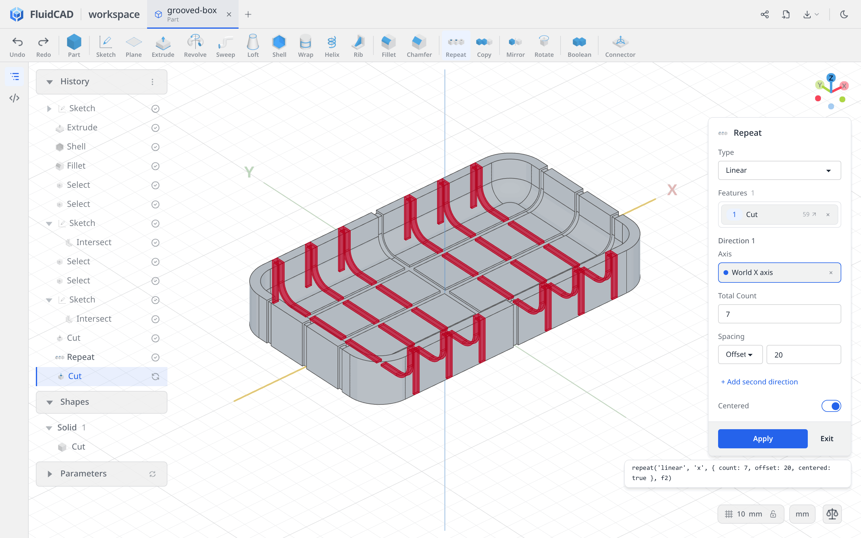
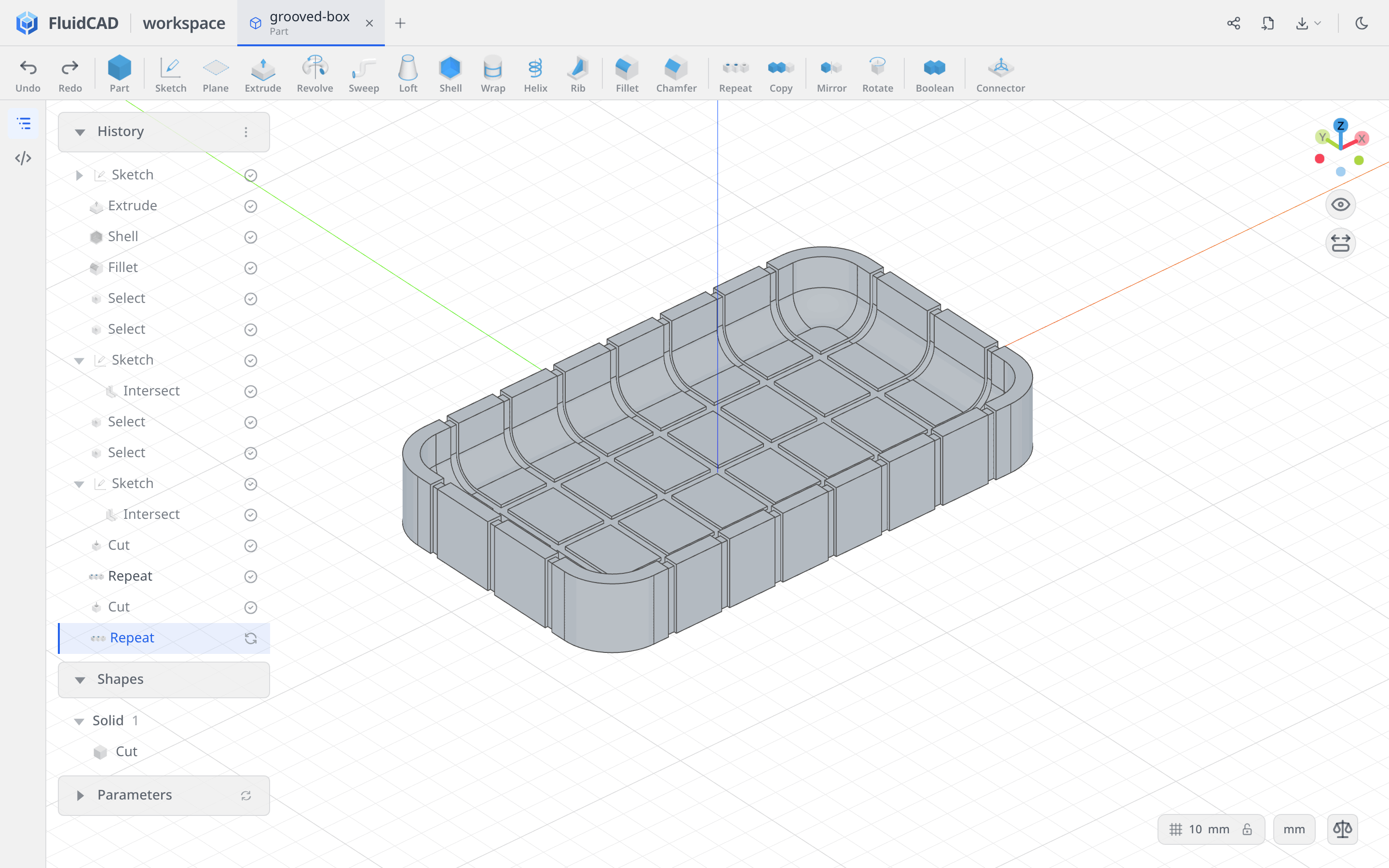
Click Apply. The box now has three grooves in one direction and seven in the other, all following the rounded interior and continuing over the rim.
Full code
The tools wrote the model into grooved-box.fluid.js. Open the code editor with the </> button on the left rail or Ctrl+B to inspect it. This listing keeps the same operations with tidier names and comments.
Show the full code
import { arc, cut, extrude, fillet, intersect, line, origin, repeat, select, shell, sketch } from 'fluidcad/core';
import { coincident, distance, equal, horizontal, midpoint, radius, tangent, vertical } from 'fluidcad/constraints';
import { face } from 'fluidcad/filters';

// Centered rounded Rectangle: W 170, H 100, R 18.
sketch('xy', () => {
  const l1 = line([-67, -50], [67, -50]);
  const a1 = arc([67, -50], [85, -32], [67, -32]);
  const l2 = line([85, -32], [85, 32]);
  const a2 = arc([85, 32], [67, 50], [67, 32]);
  const l3 = line([67, 50], [-67, 50]);
  const a3 = arc([-67, 50], [-85, 32], [-67, 32]);
  const l4 = line([-85, 32], [-85, -32]);
  const a4 = arc([-85, -32], [-67, -50], [-67, -32]);
  coincident(l1.end(), a1.start());
  coincident(a1.end(), l2.start());
  coincident(l2.end(), a2.start());
  coincident(a2.end(), l3.start());
  coincident(l3.end(), a3.start());
  coincident(a3.end(), l4.start());
  coincident(l4.end(), a4.start());
  coincident(a4.end(), l1.start());
  tangent(l1, a1);
  tangent(a1, l2);
  tangent(l2, a2);
  tangent(a2, l3);
  tangent(l3, a3);
  tangent(a3, l4);
  tangent(l4, a4);
  tangent(a4, l1);
  horizontal(l1);
  horizontal(l3);
  vertical(l2);
  vertical(l4);
  equal(a1, a2);
  equal(a1, a3);
  equal(a1, a4);
  distance(l4, l2, 170);
  distance(l1, l3, 100);
  radius(a1, 18);
  midpoint(origin(), a4.center(), a2.center());
});

const e = extrude(23.6);

// Remove the top face, then round the inside.
const sh = shell(-5, e.endFaces());
fillet(8, sh.internalEdges());

// Intersect the side faces, rim and tangent interior; leave out the underside.
const rim = select(face().onPlane(e.endFaces()));
const interior = select(face().edgeCount(8).below(e.startFaces()).withTangents());
const sideProfile = sketch('yz', () => {
  intersect(e.sideFaces(), rim, interior);
});

const rim2 = select(face().onPlane(e.endFaces()));
const interior2 = select(face().edgeCount(8).below(e.startFaces()).withTangents());
sketch('xz', () => {
  intersect(e.sideFaces(), rim2, interior2);
});

// Positive thickness cuts into the material for these intersection profiles.
const grooveX = cut(3).symmetric().thin(1);
repeat('linear', 'y', { count: 3, offset: 25, centered: true }, grooveX);

const grooveY = cut(3, sideProfile).symmetric().thin(1);
repeat('linear', 'x', { count: 7, offset: 20, centered: true }, grooveY);
What you practiced
- Rectangle → Rounded + Centered — a fully constrained outline from a center, width, height, and radius.
- Shell and Fillet — remove the top face, then round the internal floor-to-wall transition.
- Face groups — use tangent and feature selections to collect the surfaces for an intersection.
- Intersect — capture two fixed cross-sections before changing the source solid.
- Remove + Symmetric + Thin walls — cut a shallow strip along an open profile.
- Repeat → Linear — pattern each cut with a total count, offset spacing, and centered placement.