Building a Lantern
In this tutorial, you'll build a hexagonal lantern, based on the original design by TooTallToby. You build almost all of it from the FluidCAD workspace: the toolbar, the sketch tools, the constraint bar and the feature dialogs. Every dialog writes a line of code into your file as you apply it, so the full code at the end is what the UI produced, not something you type.
It covers the Polygon tool and its Inscribed option, construction planes stacked up the Z axis, a drafted extrusion kept as a separate solid, shelling by picking the faces to remove, projecting a model face into a sketch as fixed reference geometry, an inward Offset to make a window, a circular Repeat of a whole cut, sketching on faces the model already has, and a Loft between two faces for the roof.
The finial and the hanging ring at the very top are the exception: spheres, translate() and offset axes have no tool yet, so Step 5 is typed into the code editor.
Before you start
Open a workspace and create a new part file: click + in the top bar and type lantern.fluid.js. The new tab opens on an empty scene. The screenshots use the light theme; the sun/moon button at the top right switches it.
A few UI habits you will use throughout:
- Ctrl+click adds an entity to the current selection. A plain click replaces it.
- The constraint bar appears under the toolbar while you sketch. Its buttons are icons; hover one for its name. A button lights up only when the current selection makes sense for it.
- The DOF pill at the bottom of the viewport counts the degrees of freedom left in a sketch and turns into Fully constrained when you are done. Every sketch in this tutorial ends there.
- Every feature dialog shows the statement it is about to write, just under the dialog. Apply (or Enter) writes it; Exit / Cancel (or Escape) discards it.
- A construction plane you create leaves the viewport once a sketch has used it. It stays pickable from its timeline row, and the eye on that row draws it again; this tutorial simply makes a plane and sketches on it in one go, as each of Steps 1 and 4 does.
Step 1: The middle body
The lantern's cage is a hexagonal prism that tapers as it rises and is hollow inside. It starts 24 mm up, to leave room for the base underneath.
A plane 24 mm up
Click Plane in the toolbar and click the XY origin plane for the base. Set Offset to 24. The yellow quad and its arrow preview the new plane, and the statement reads plane('xy', 24).
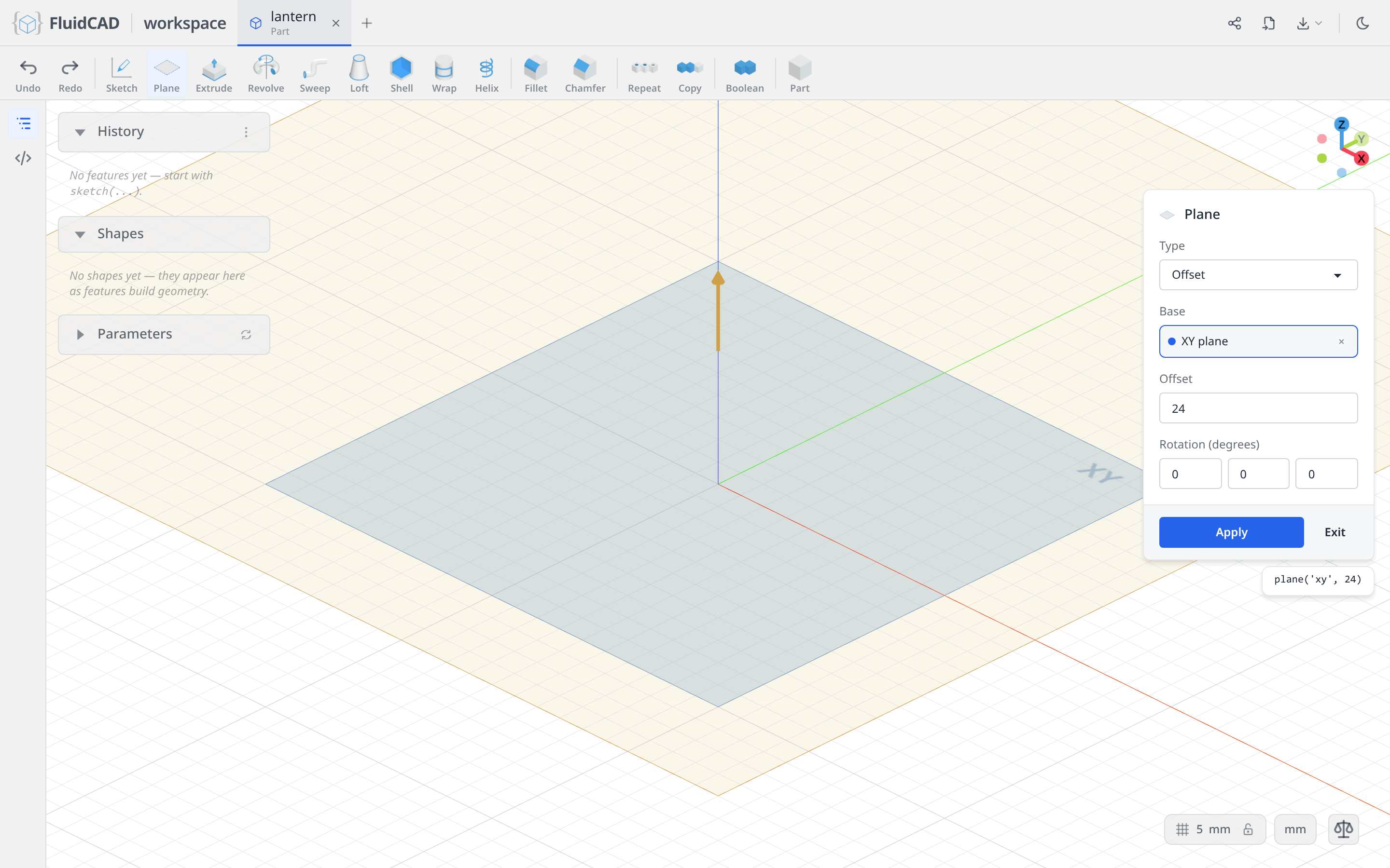
Click Apply.
Sketch on it
Click Sketch. The dialog asks for a face or a plane, and the origin planes appear alongside the one you just made — the larger quad with the orange outline.
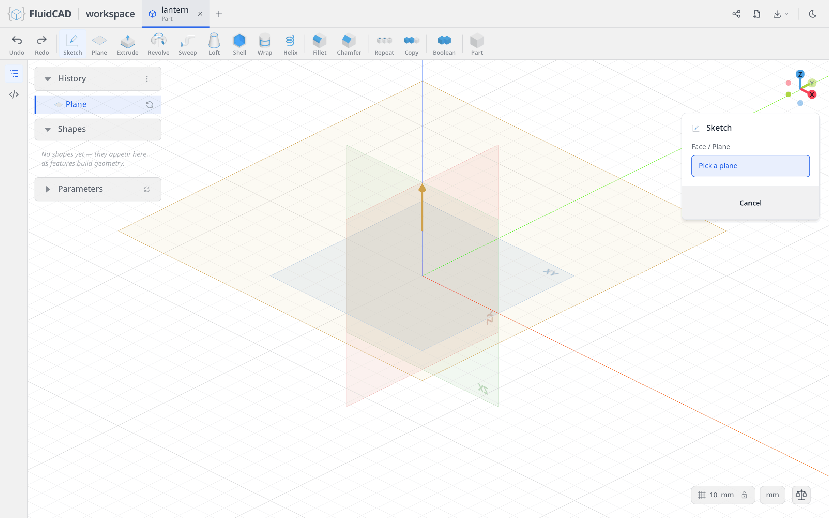
Click the new plane. The camera locks onto it, the sketch toolbar replaces the feature toolbar, and the constraint bar appears above the viewport. The chip reads Plane.
Draw the hexagon with the Polygon tool
A regular hexagon is one tool, not six lines and a pile of constraints.
Click Polygon. The button opens a small option menu asking where the guide circle sits: Circumscribed draws the sides tangent around it, Inscribed puts the corners on it. Choose Inscribed, so the diameter you type is measured across the corners.
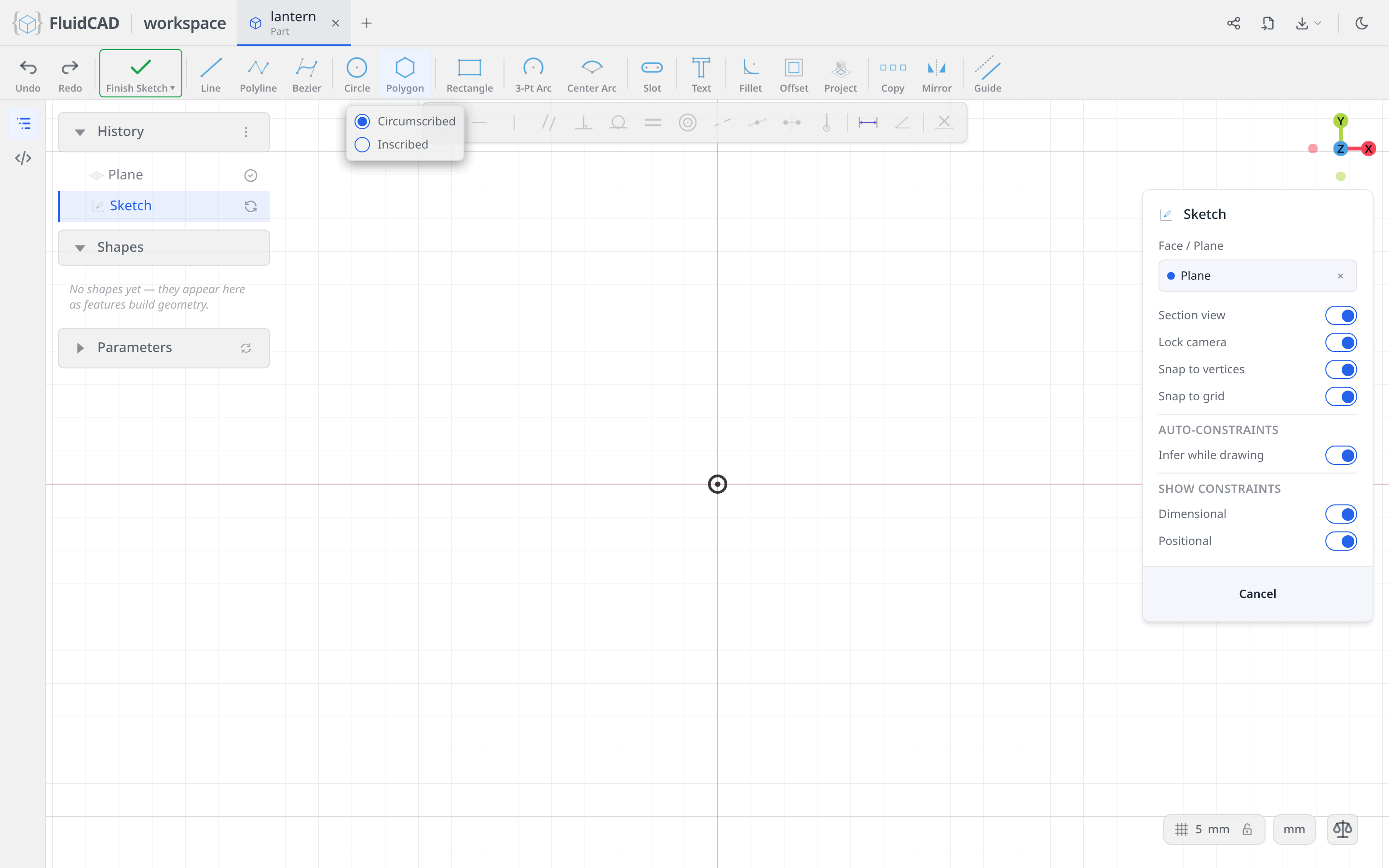
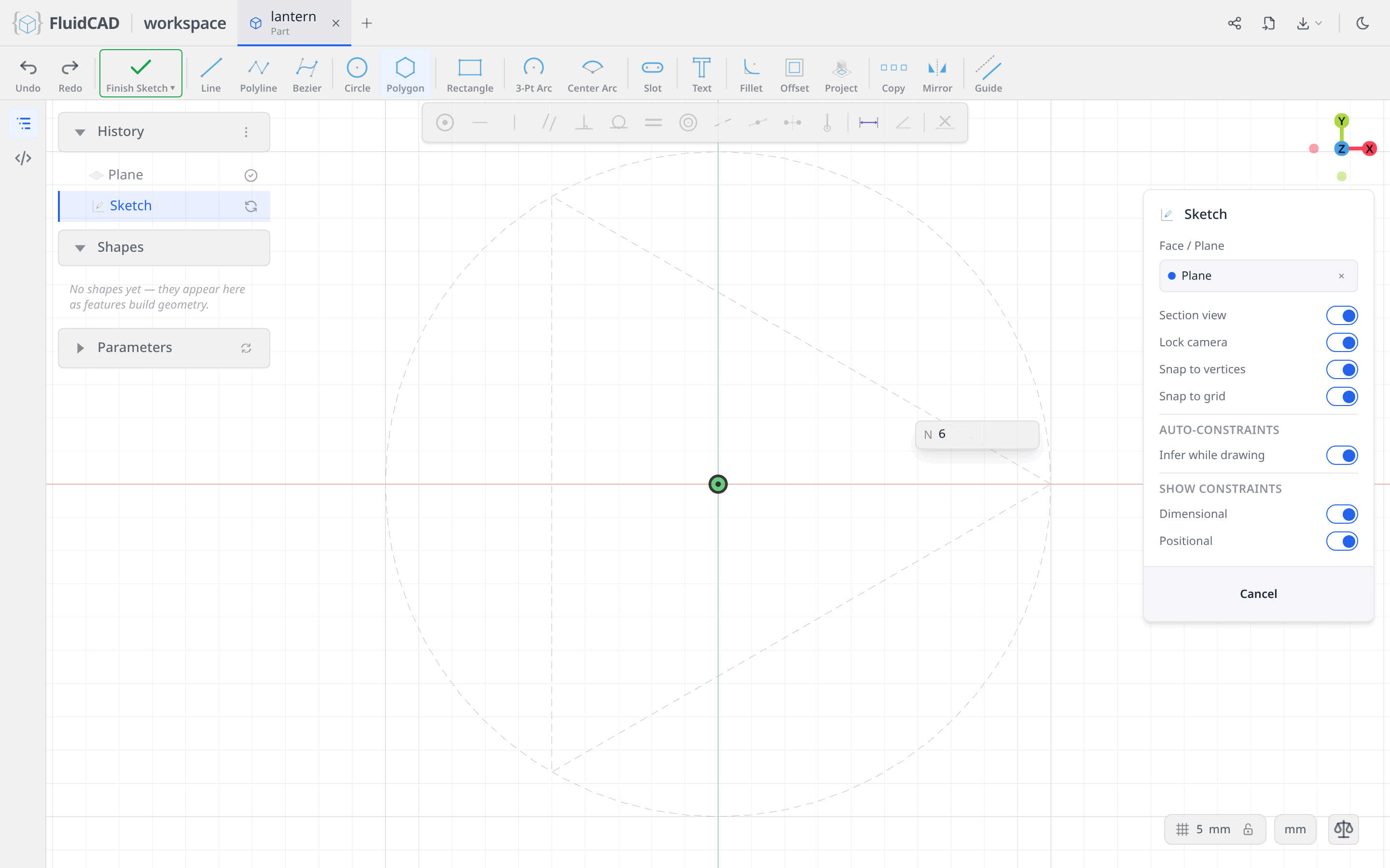
Click the origin for the centre. A ⌀ readout follows the mouse with a dashed guide circle; type 100 and press Enter.
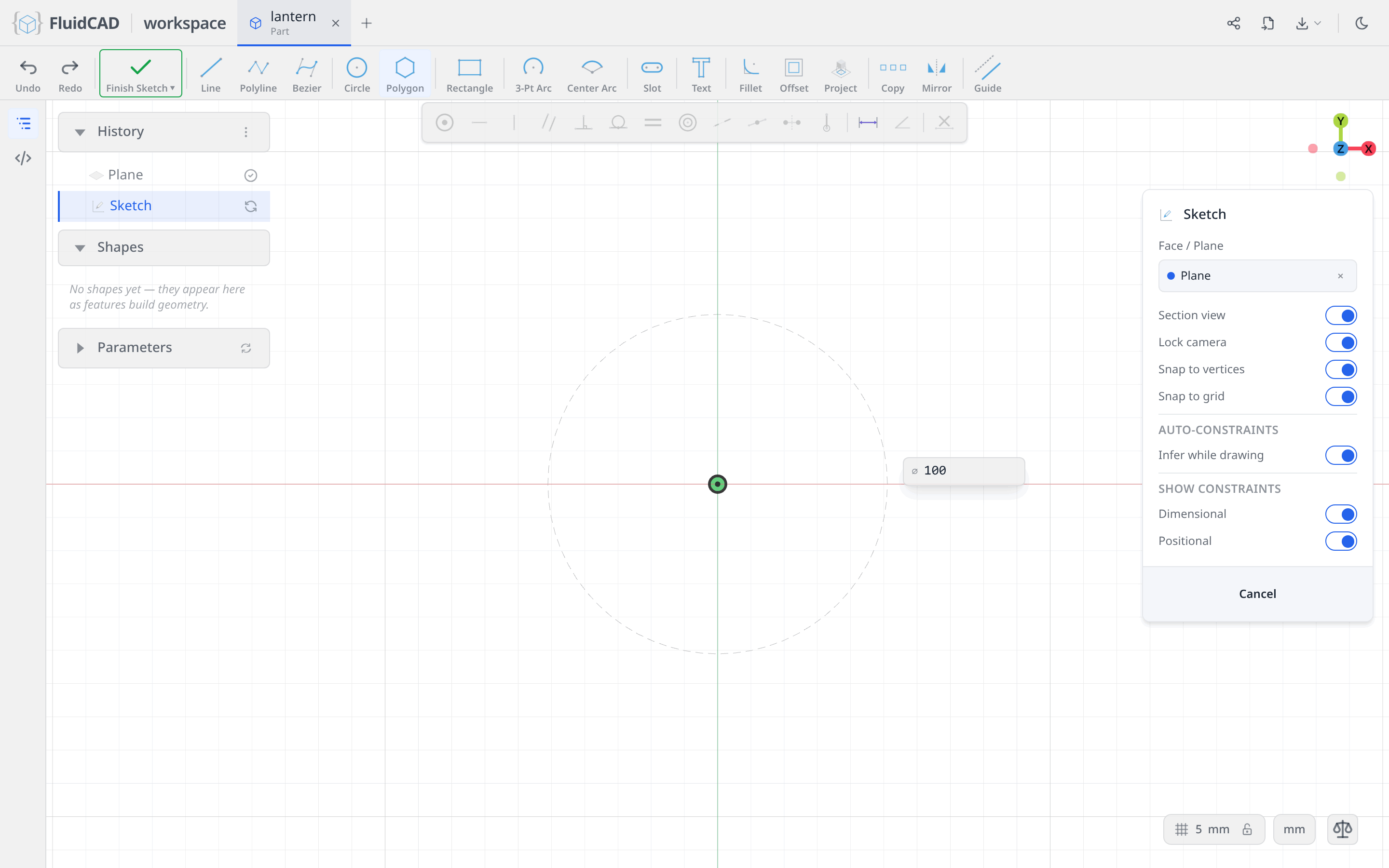
The readout switches to the number of sides. Type 6 and press Enter.
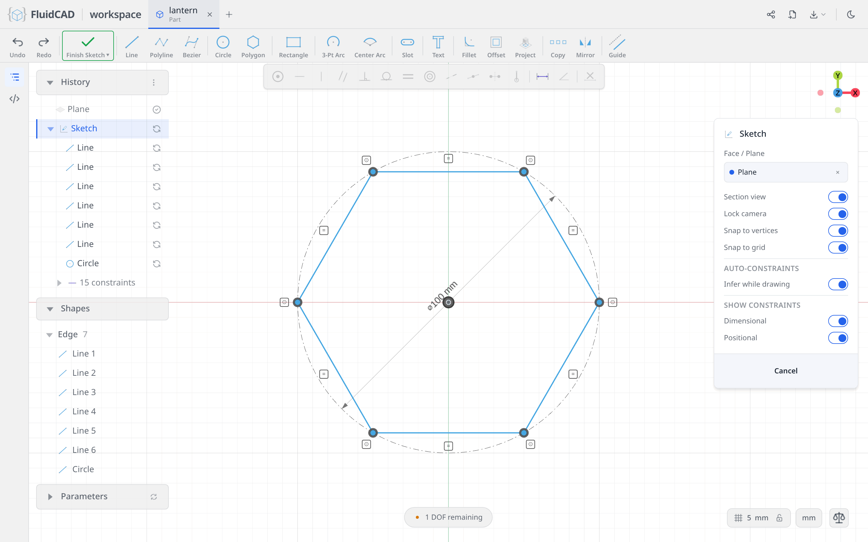
One gesture, and the hexagon arrives almost fully described: six lines, a coincident at every corner, one equal covering all six sides, all six corners coincident with a .guide() circle, the ⌀100 on that circle, and its centre on the origin. The DOF pill still reads 1 DOF remaining — nothing yet says which way round the hexagon sits.
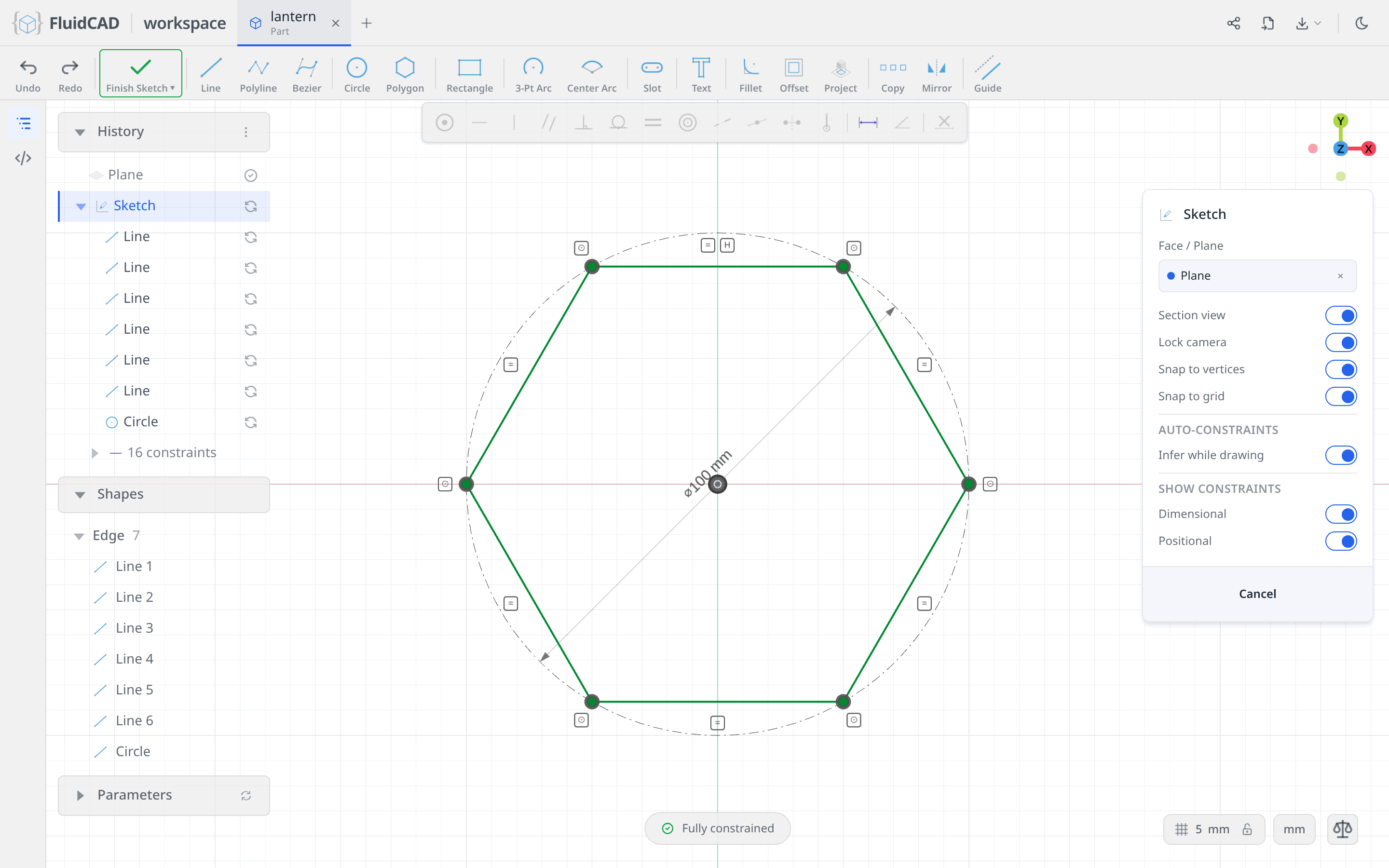
Click the top side and click Horizontal. That is the last degree of freedom.
Extrude it with a draft
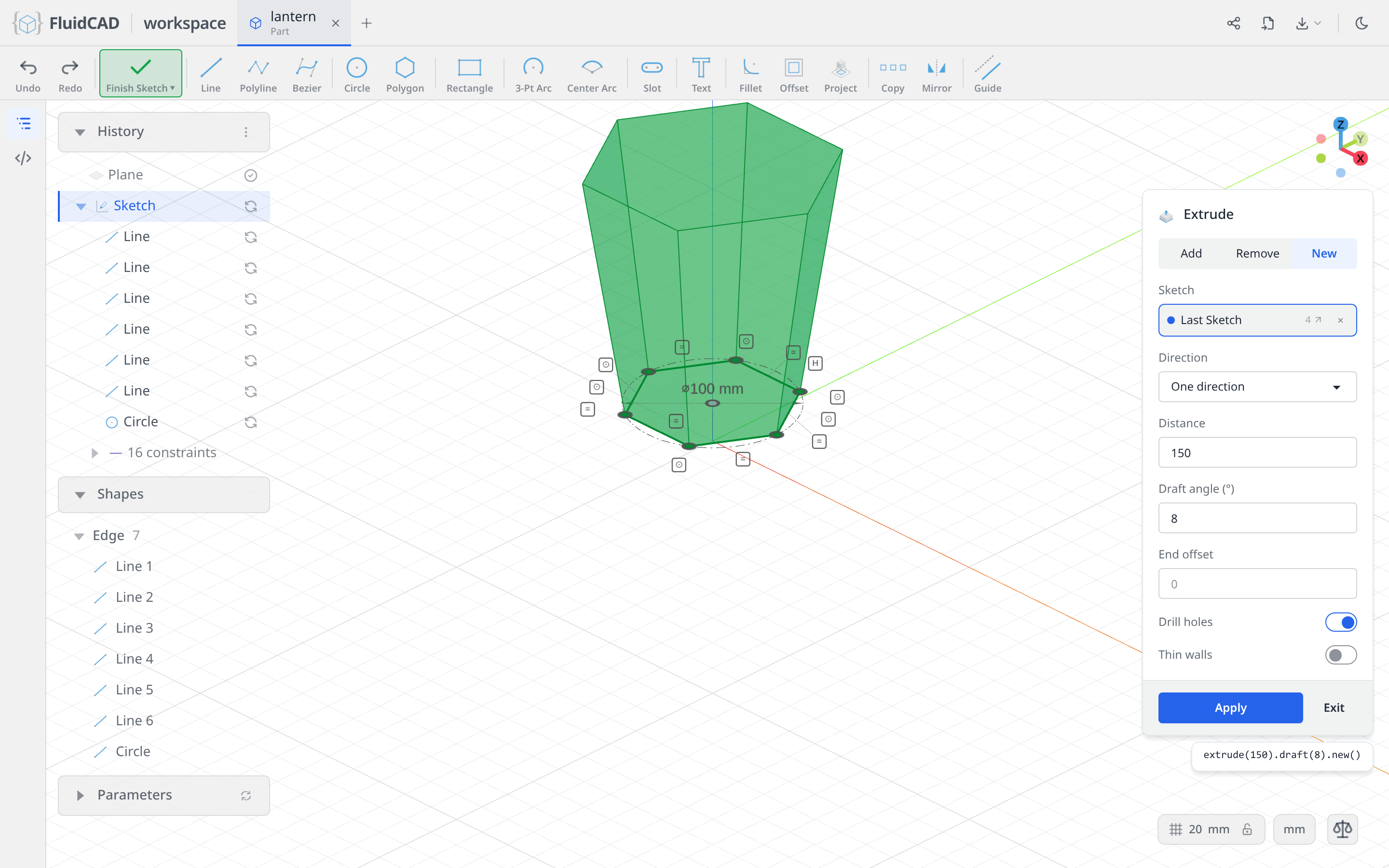
Click Extrude on the toolbar.
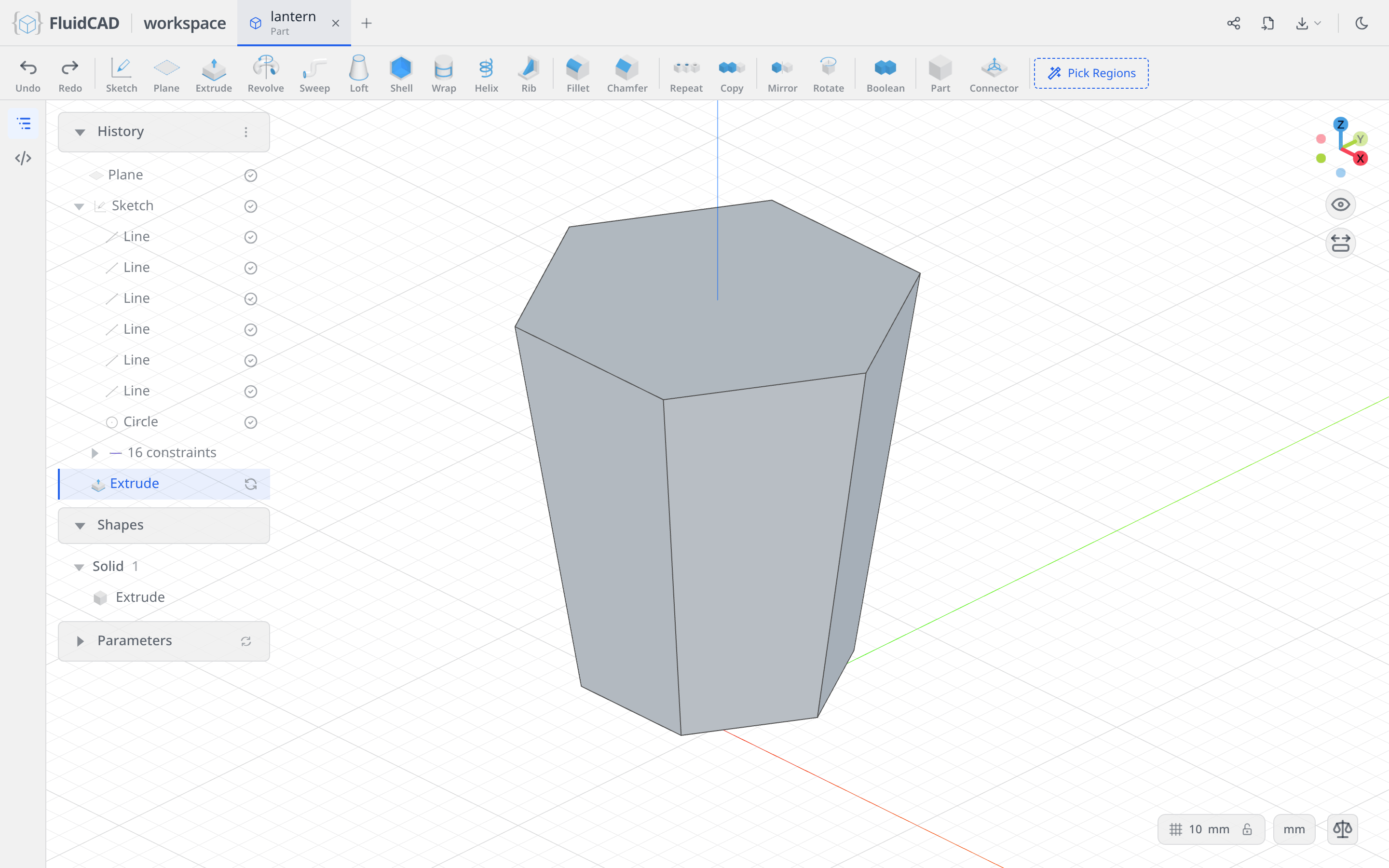
Select the New tab, set Distance to 150 and Draft angle to 8. New keeps the cage as its own solid, so the base and the top you add later cannot interfere with the faces you are about to reference. The draft is what gives the lantern its taper — the hexagon grows as it rises. The statement reads extrude(150).draft(8).new().
Click Apply.
Shell it hollow
Click Shell in the toolbar and click the top face of the prism. Rotate the view until you can see underneath and Ctrl+click the bottom face too — those are the two faces that get removed. Set Thickness to -7; the negative sign keeps the wall inside the original surface, so the outside of the lantern does not move.
The statement names the picks by the operation that made them: shell(-7, e.endFaces(), e.startFaces()).
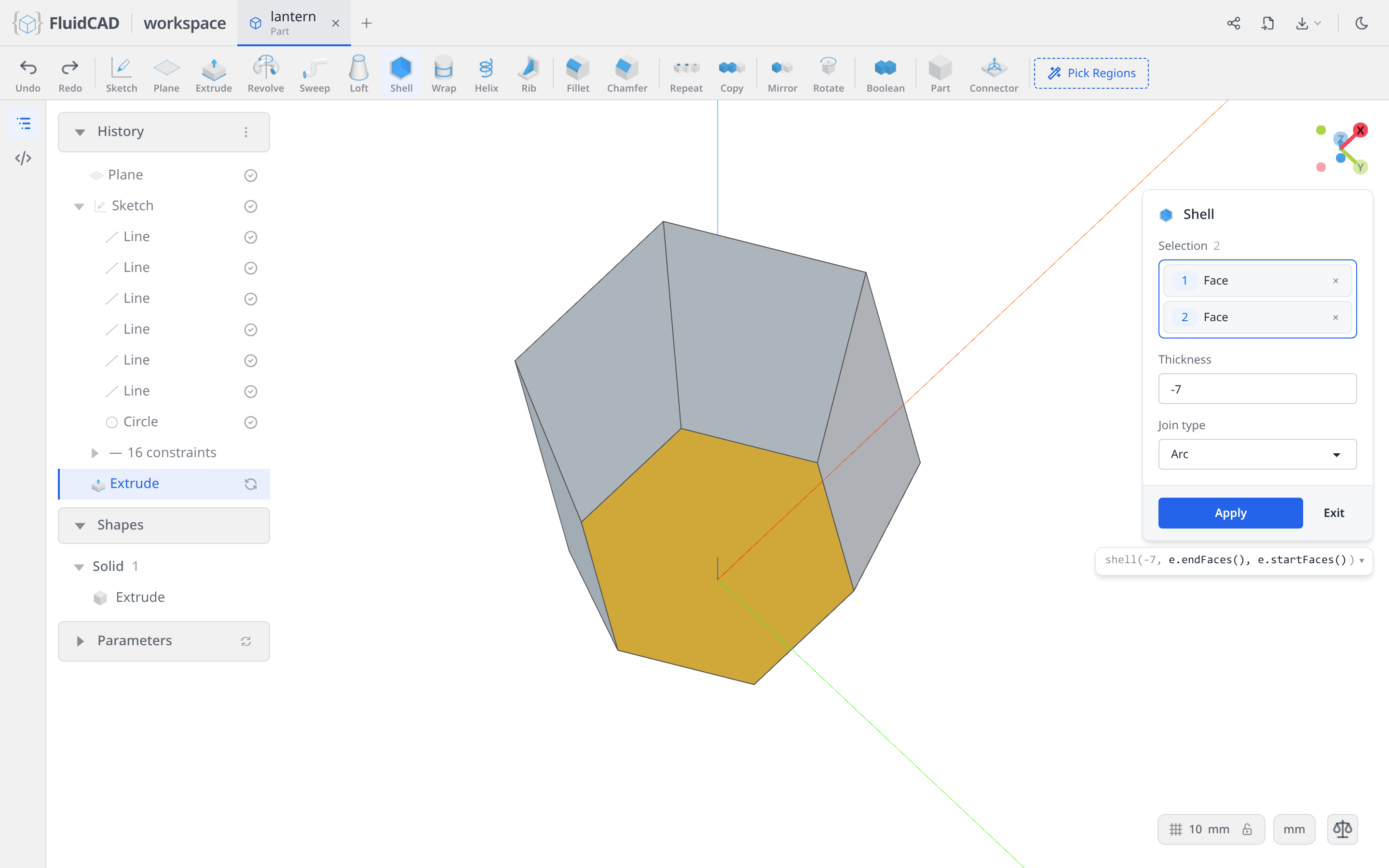
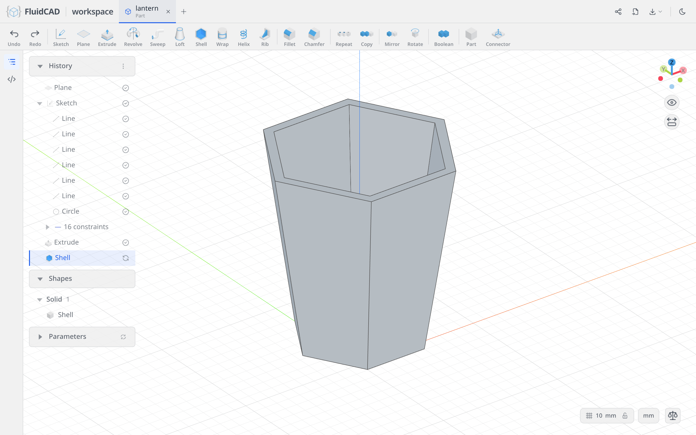
Click Apply. What is left is a 7 mm hexagonal tube.
Step 2: Cut the windows
Every side of the lantern gets a window, inset 6 mm from the edges of its face. Rather than measure that inset, project the face itself into the sketch and shrink it.
Sketch on a side face
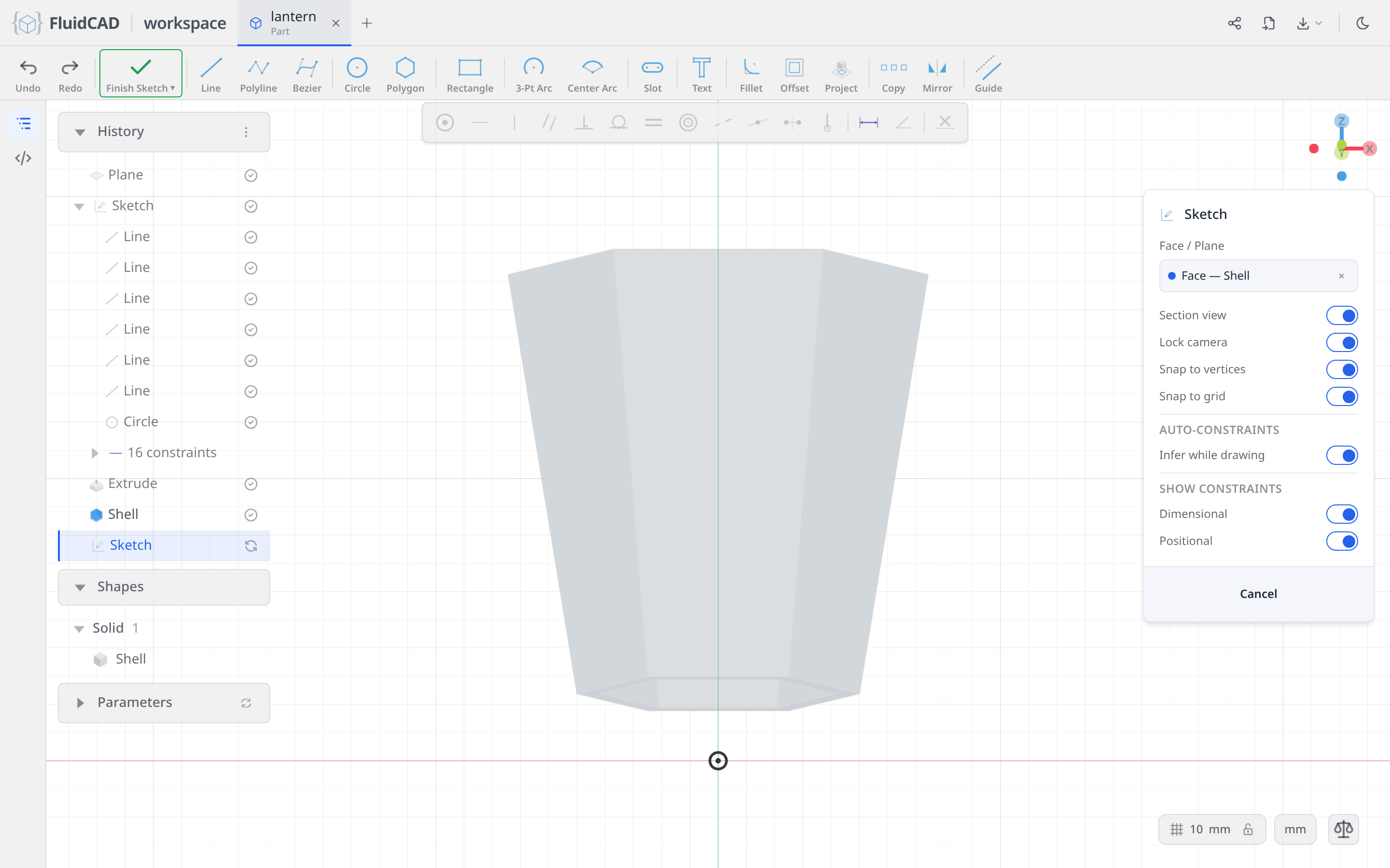
Click Sketch and click one of the side faces of the body. The chip reads Face — Shell: FluidCAD remembered which operation produced that face, so the sketch follows the body if you change it later. The camera looks straight at the face, and the face itself is drawn dimmed behind the sketch.
Project the face
Pick the Project tool from the sketch toolbar. It suspends sketch editing so you can pick in the free 3D view; click the same side face. The statement reads project(e.sideFaces(1)) — a rule, not a fixed index, so it survives edits.
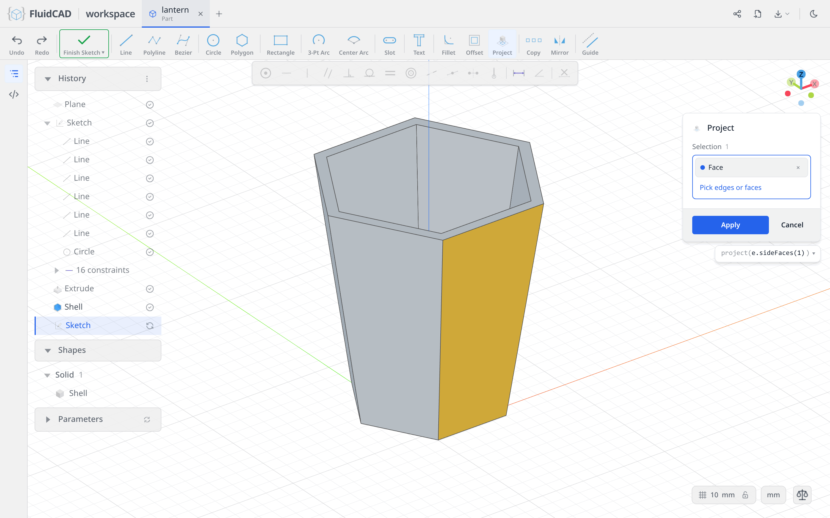
Click Apply. Four projected edges arrive, exactly on the outline of the face. They come in fixed: they add no freedom to the sketch and other geometry can lean on them, which is why the pill still reads Fully constrained.
Now make them reference geometry. Click one projected edge, Ctrl+click the other three, and click Guide.
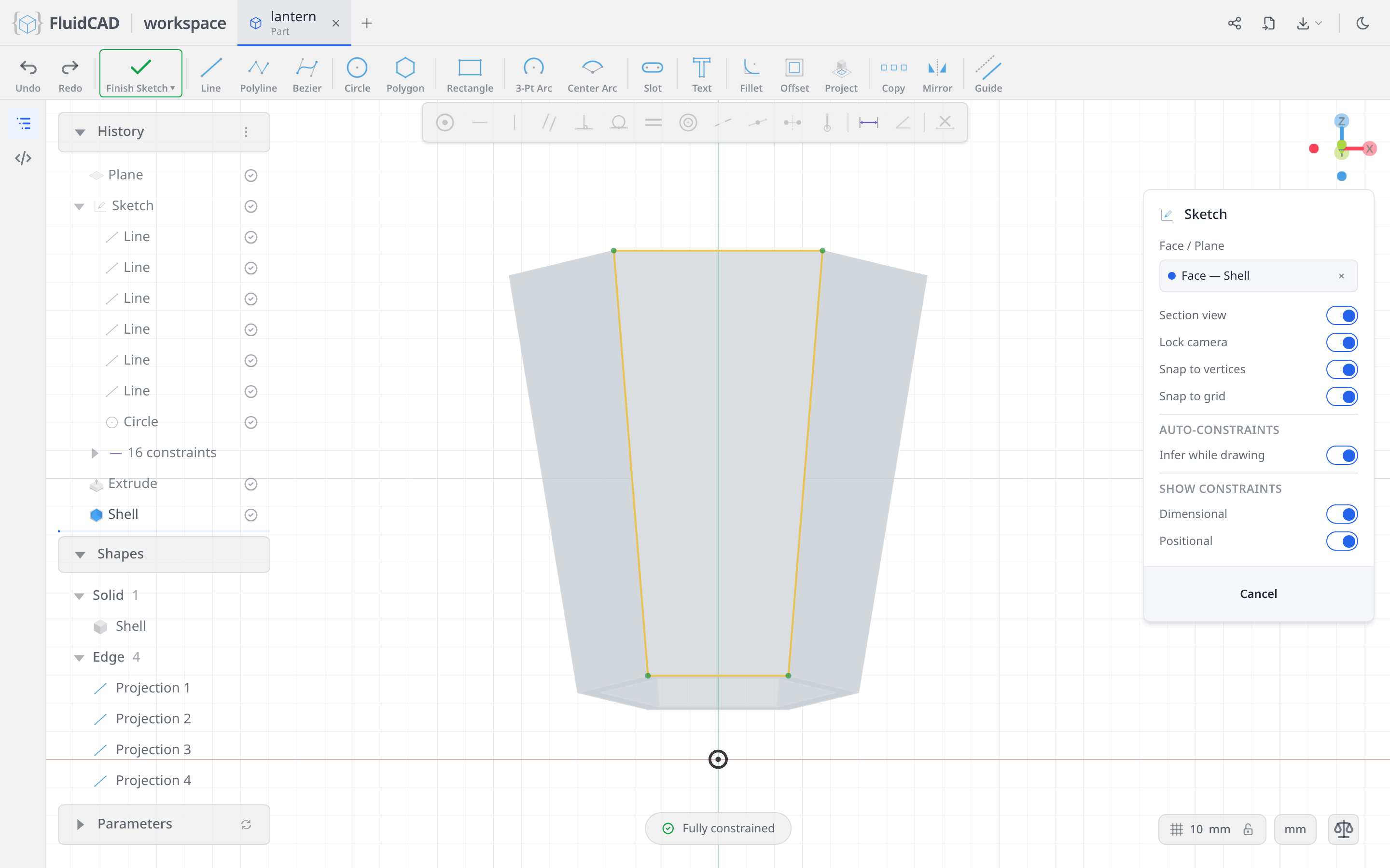
The statement grows a .guide(): project(e.sideFaces(1)).guide(). Guides steer other statements but never become part of a profile, so the outline of the face will not be cut — only what you derive from it.
Offset it inward
Pick the Offset tool. Click one guide edge, then Ctrl+click the other three so the whole loop is in the Selection list. Set Distance to -6 — negative offsets run inward. The statement collapses the four picks back to the projection they came from: offset(-6, pj).
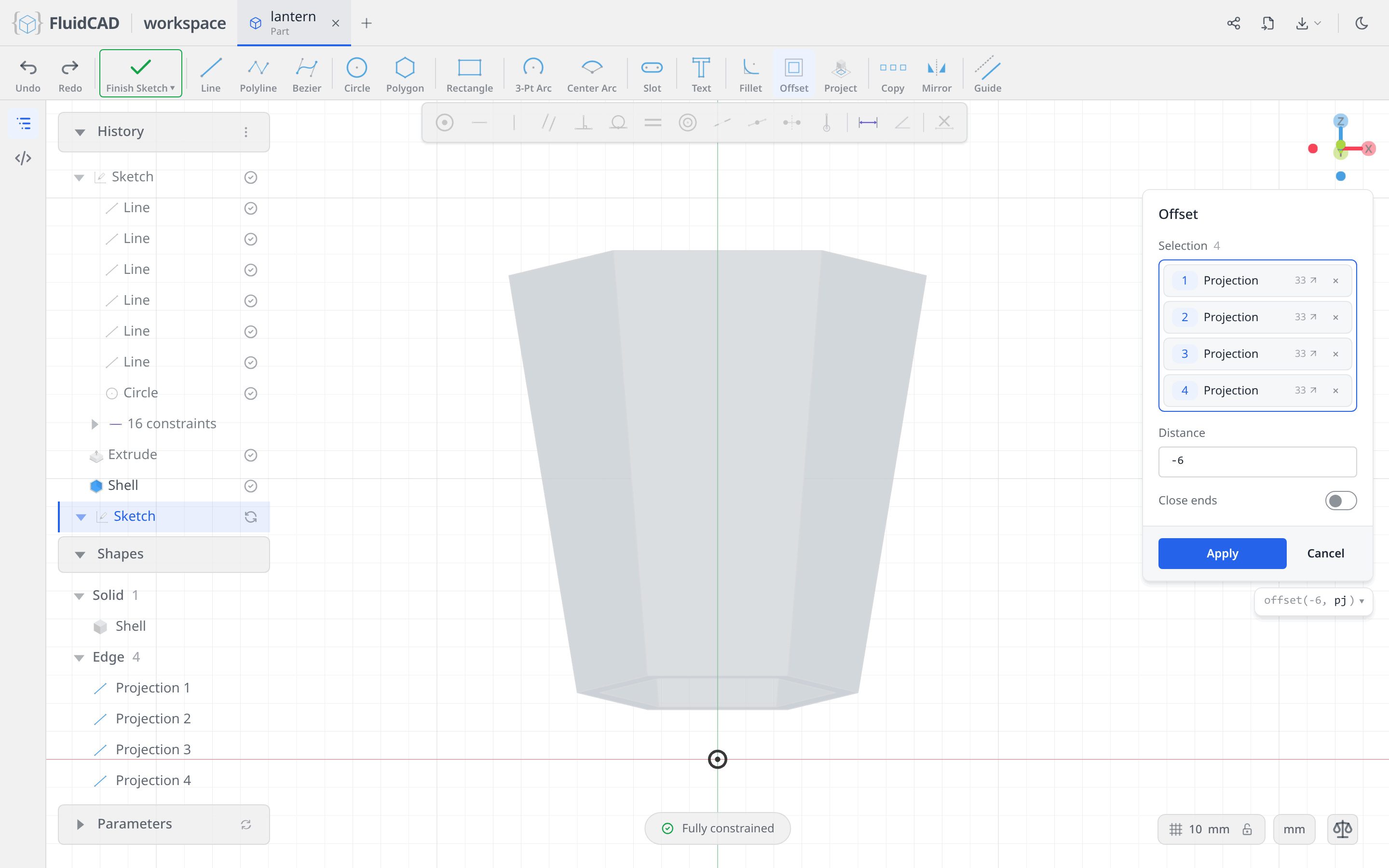
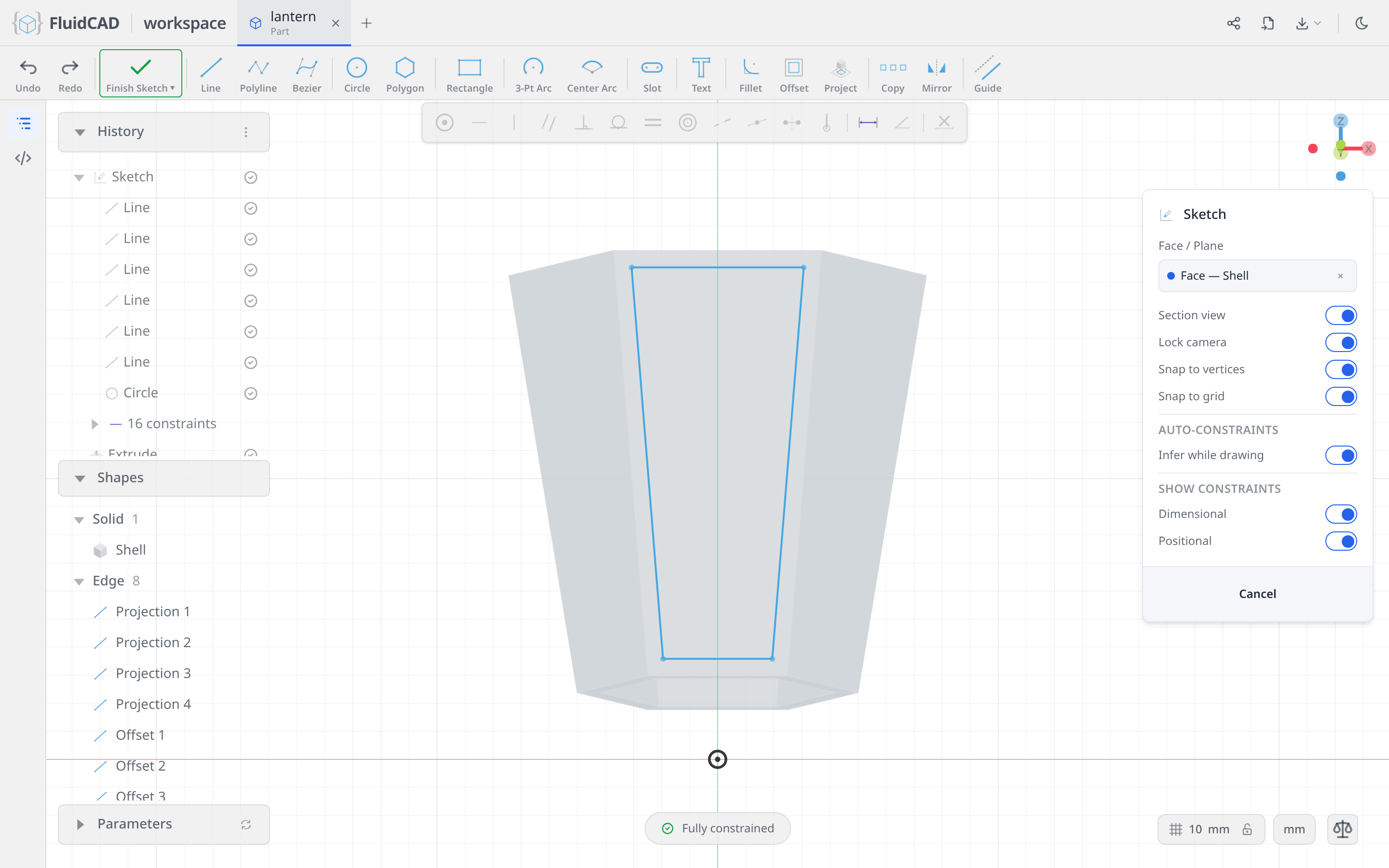
Click Apply. The inset loop is the sketch's only real profile, and it is exactly the window.
Cut it, then repeat it around
Click Extrude on the toolbar. Select the Remove tab and set Depth to 7 — the wall thickness. A cut runs opposite the sketch normal, so 7 mm from the outer face is exactly through the wall. The red ghost is the material about to disappear and the statement is cut(7).
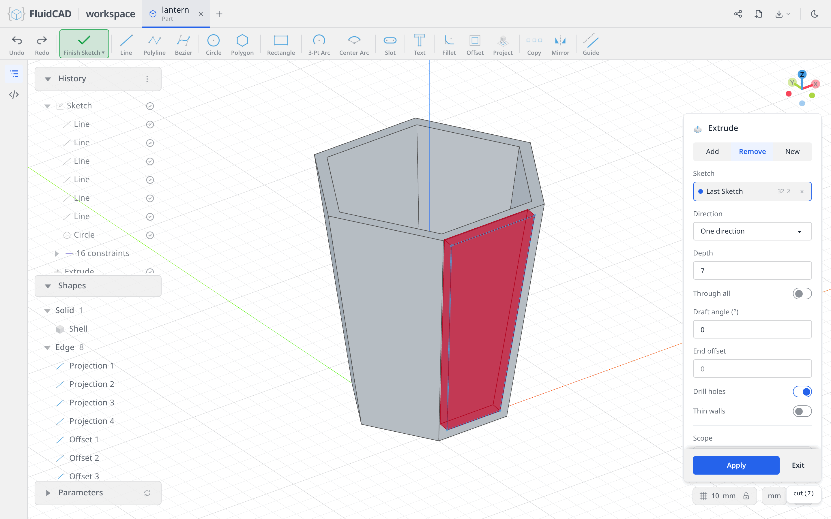
Click Apply.
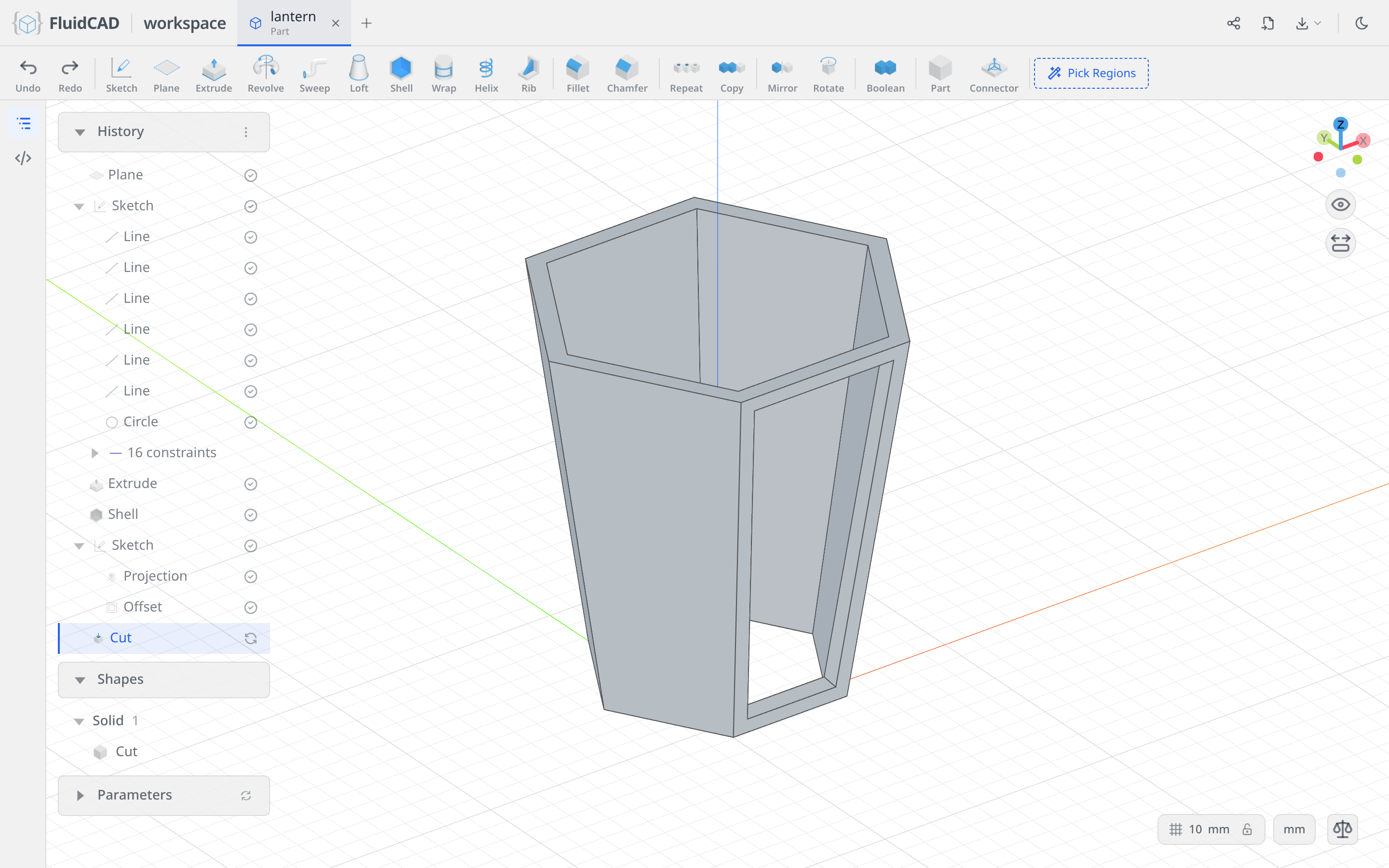
Click Repeat in the toolbar and set Type to Circular. Repeat takes its targets from the History panel: click the Cut row, and it lands in the Features slot. The axis defaults to World Z, which is what you want. Set Total Count to 6 and leave the angle on Total 360, so the six instances spread evenly all the way round.
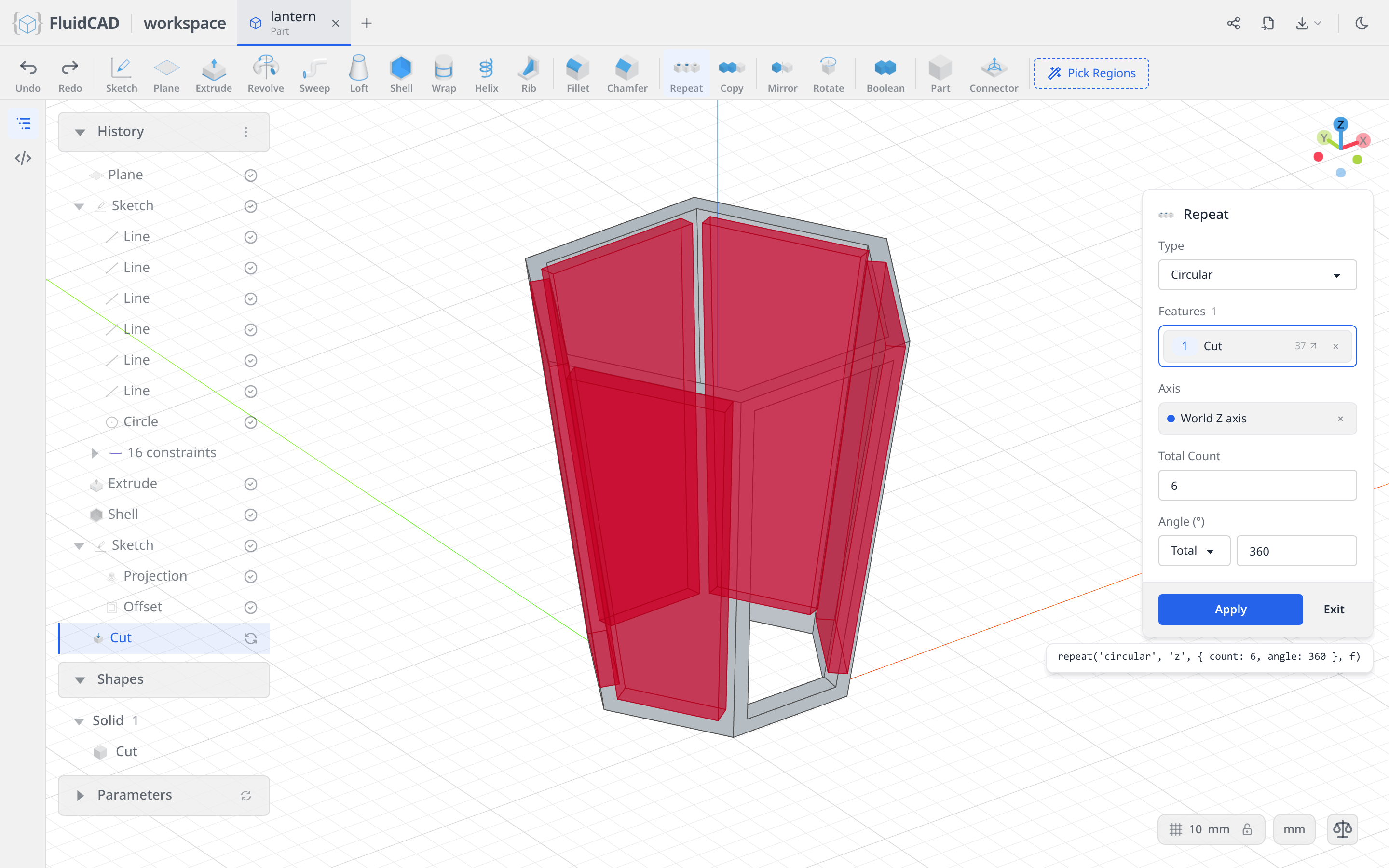
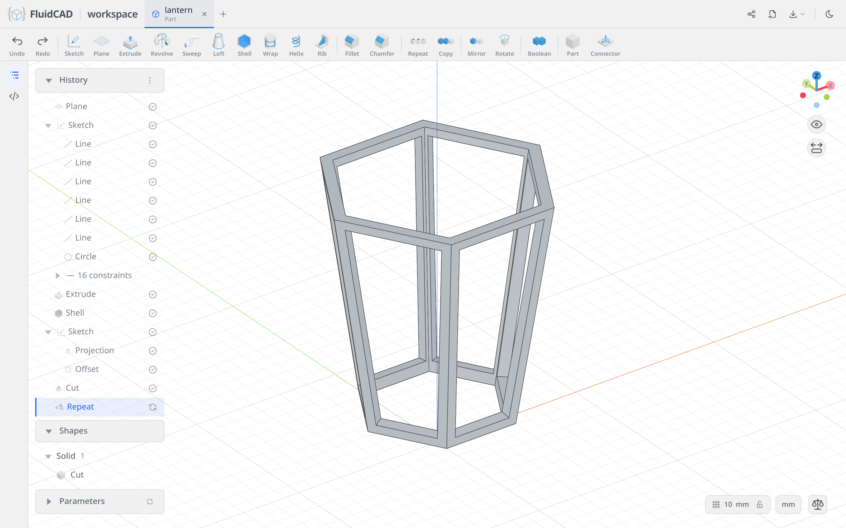
Click Apply. Repeat re-applies the operation, not the solid, so each face gets its own window cut through its own wall.
Step 3: The base
The base is two stacked hexagonal tiers, each 12 mm tall, that lift the cage off the ground.
A wider hexagon on the XY plane
Click Sketch and click the XY origin plane — the horizontal one, at z = 0.
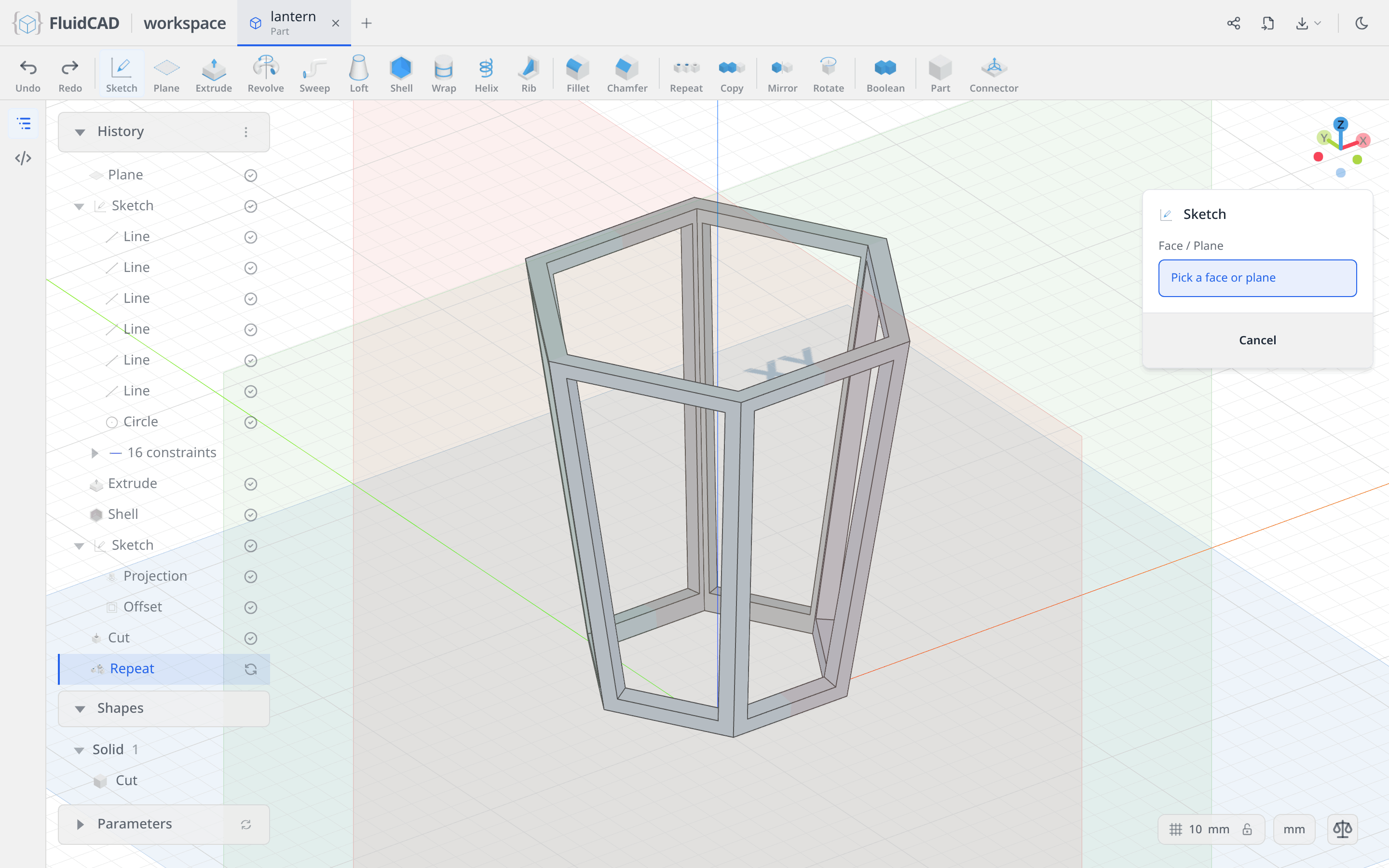
Draw the same way as before: Polygon, origin, ⌀150, 6 sides, then a Horizontal on the top side to spend the last degree of freedom.
Extrude, Distance 12, Add tab. The green ghost is the slab.
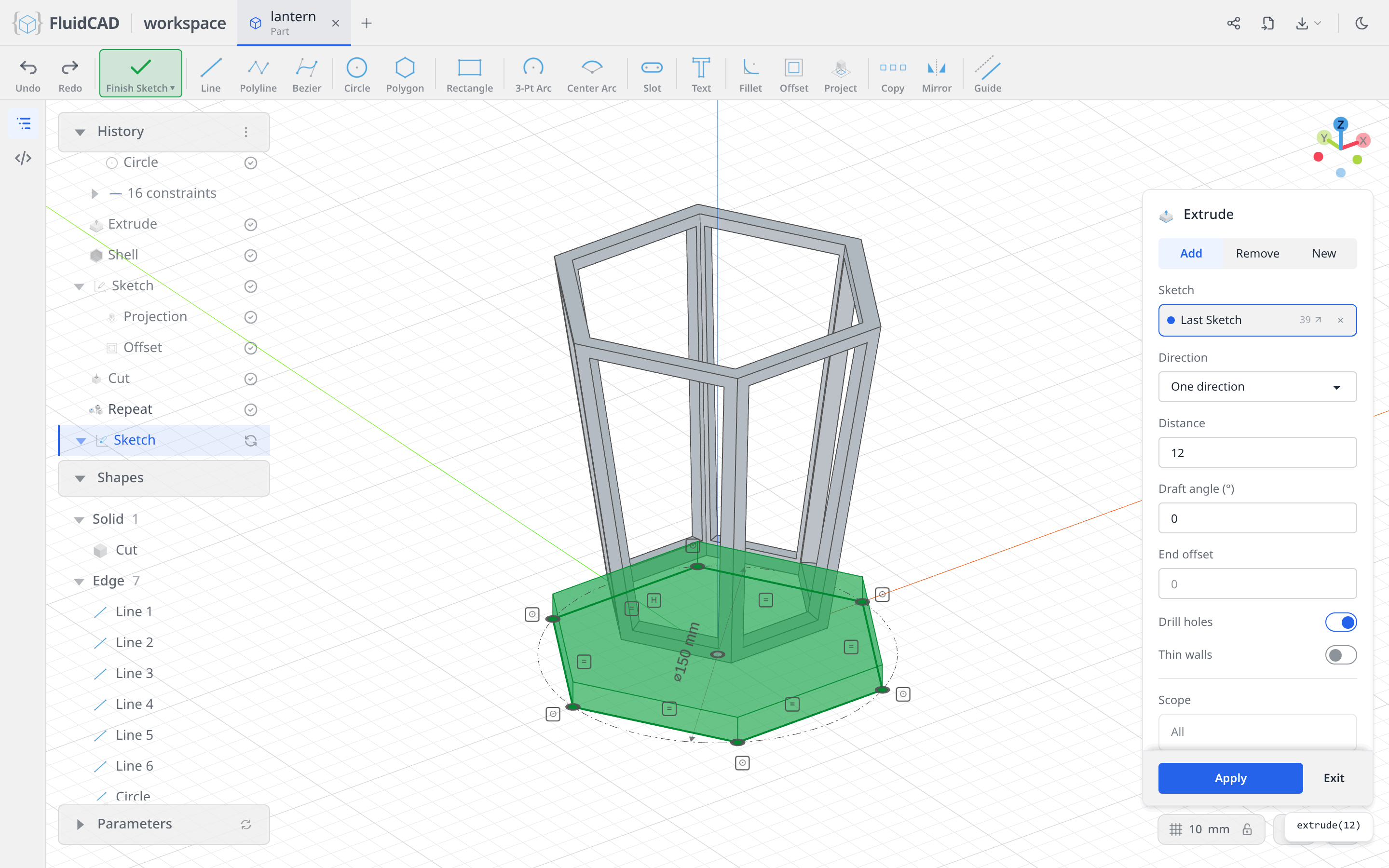
Click Apply.
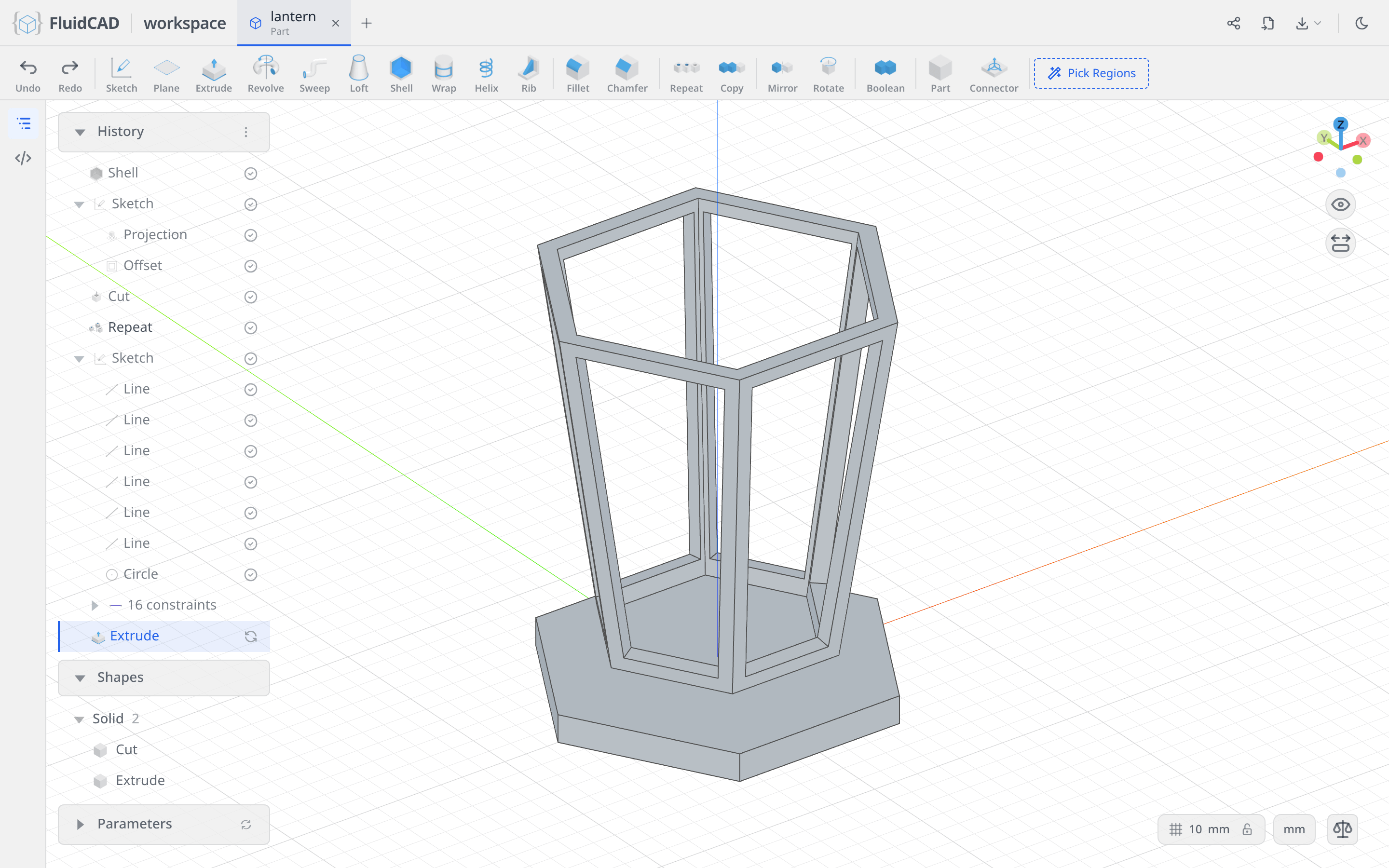
A narrower hexagon on top of it
Click Sketch again and this time click the top face of the slab. The chip reads Face — Extrude.
Draw a Polygon on the origin, ⌀115, 6 sides, Horizontal on the top side, then Extrude, Distance 12.
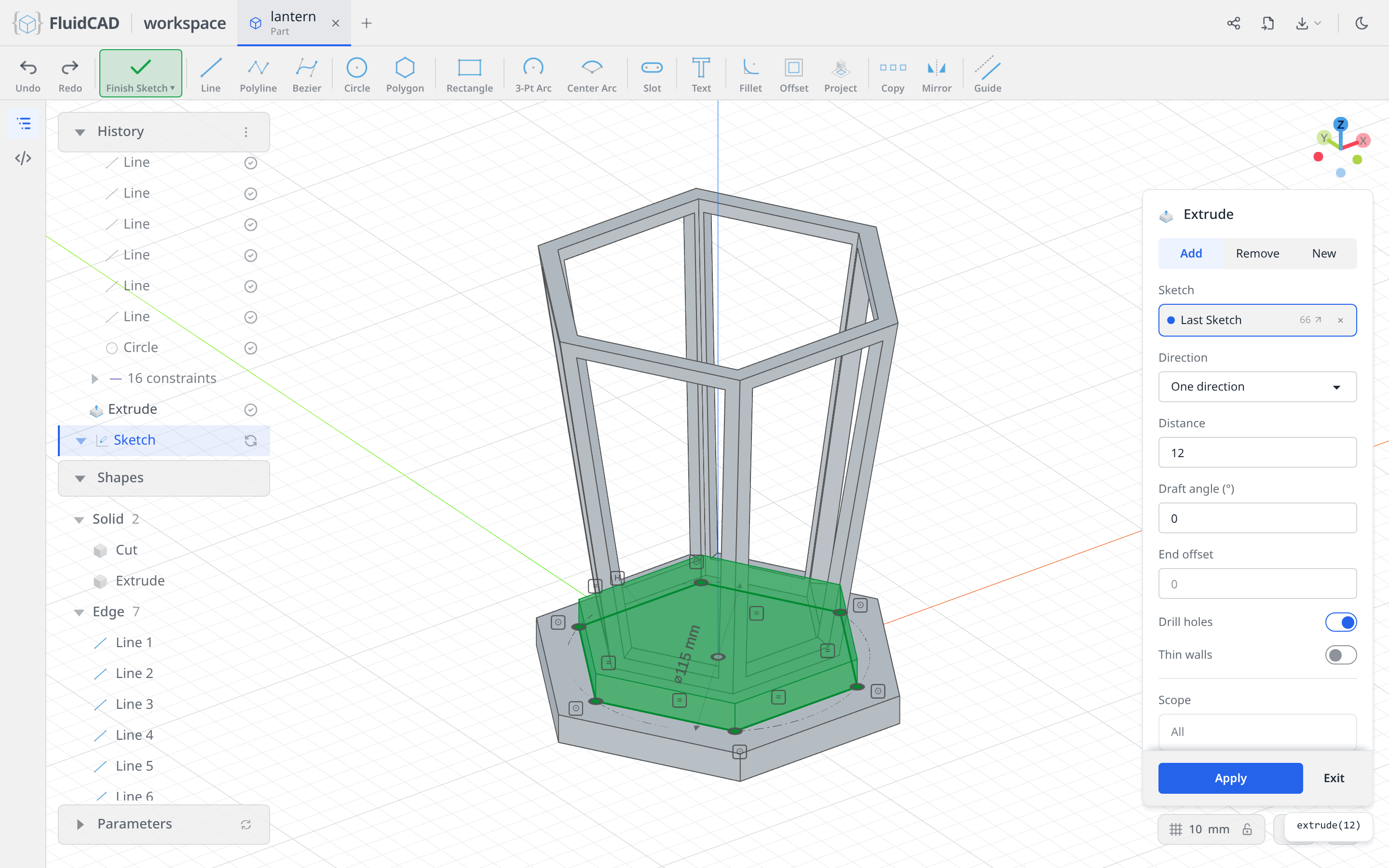
Click Apply. The upper tier reaches z = 24, meets the bottom of the cage and fuses with it — the whole lantern is one solid from here on.
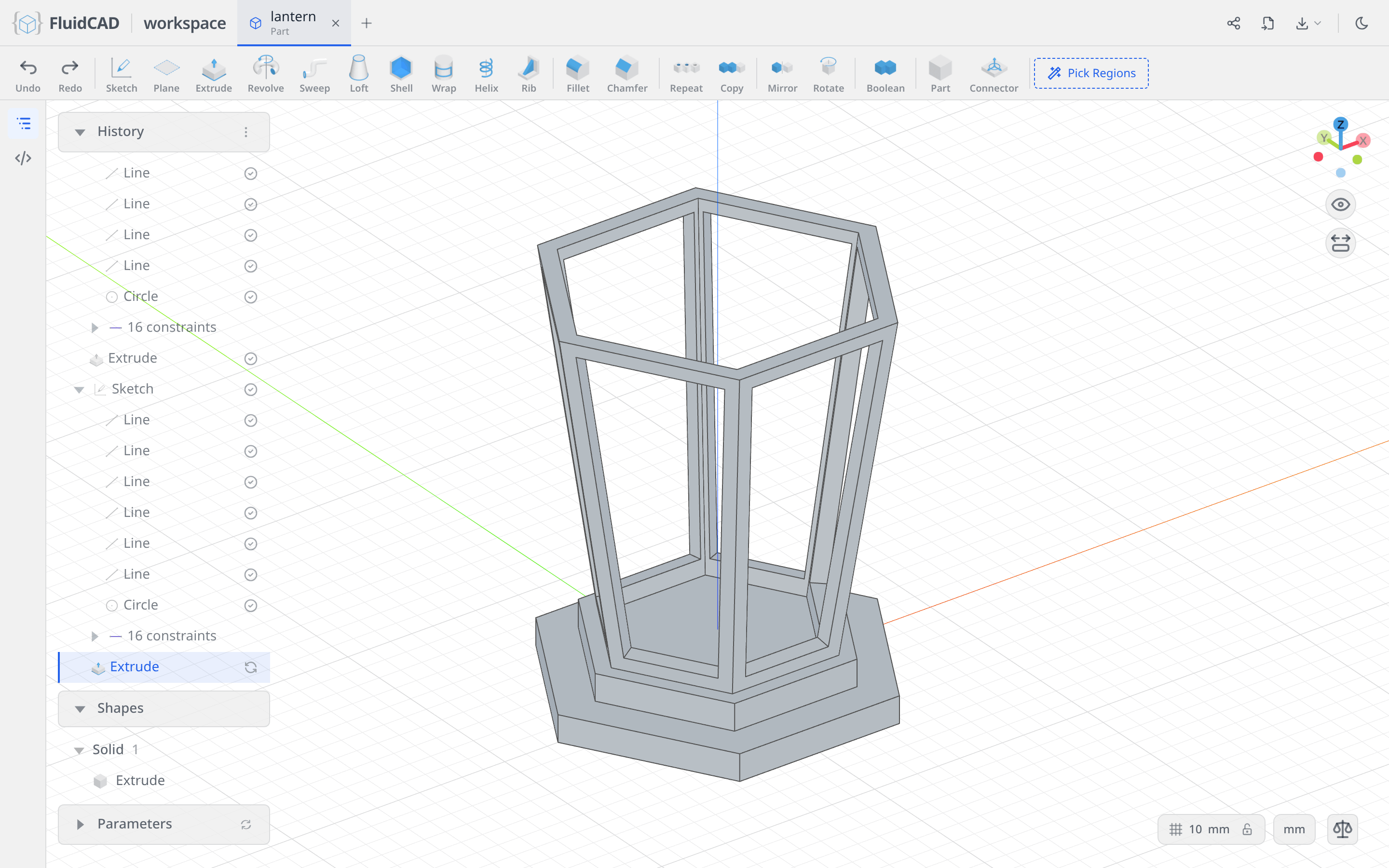
Step 4: The top and the lofted roof
The top is a wide cap over the cage, a small hexagonal tip floating above it, and a loft joining the two.
The cap
Click Plane, pick XY and set Offset to 174 — 24 plus the 150 mm of cage, so the plane lands on top of the body. Apply, then click Sketch and pick the new plane.
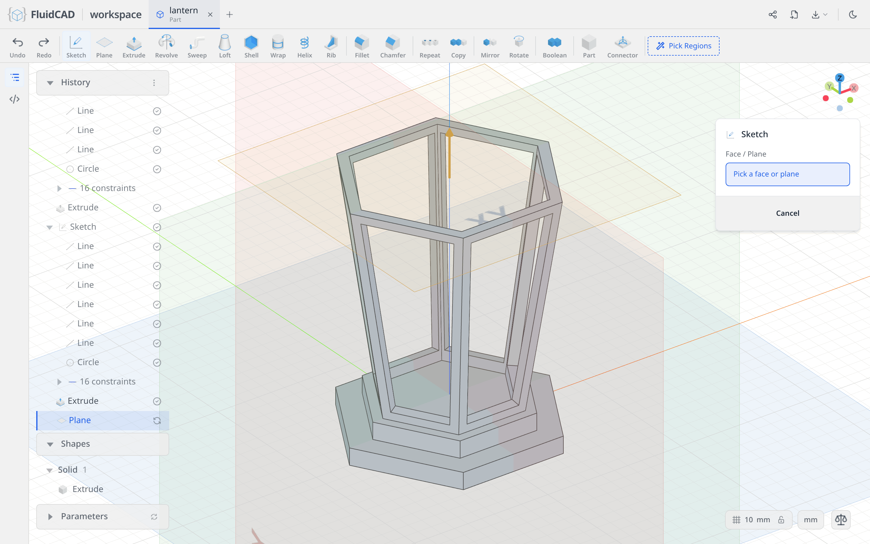
Polygon, origin, ⌀165, 6 sides, Horizontal. Then Extrude, Distance 12, Apply.
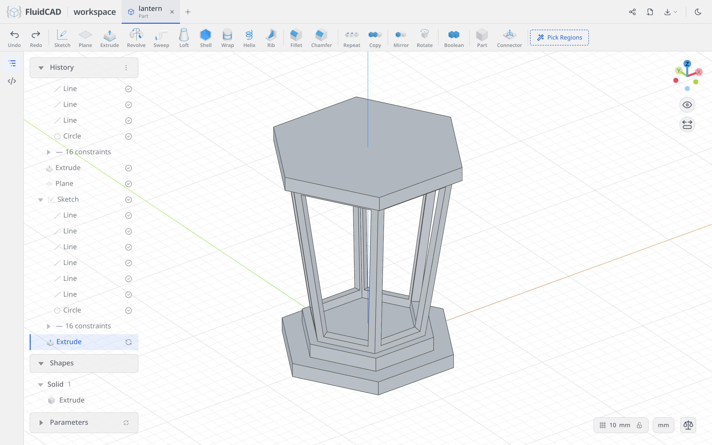
The tip
Click Plane again, XY, Offset 238. Apply, Sketch on it, and draw a Polygon on the origin, ⌀50, 6 sides, Horizontal.
Extrude, Distance 12. The tip floats 52 mm above the cap for now — nothing joins them yet.
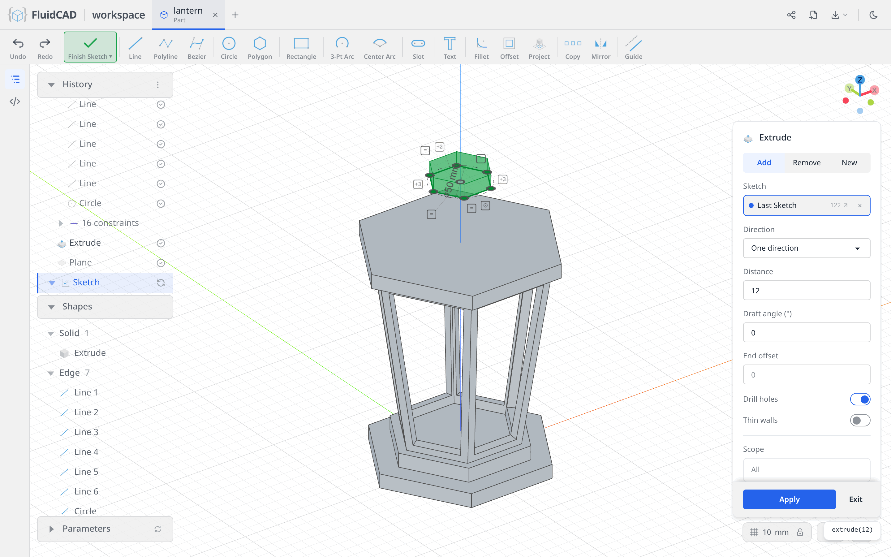
Click Apply.
Loft the roof between them
Click Loft in the toolbar. The dialog wants profiles in loft order, and a profile can be a face you pick in the 3D view. Click the top face of the cap, then rotate the view until you can see under the tip and click the bottom face of the tip.
The two chips are the two ends of the roof, and the statement names them by the operations that made them: loft(e3.endFaces(), e4.startFaces()). The green ghost is the surface they describe.
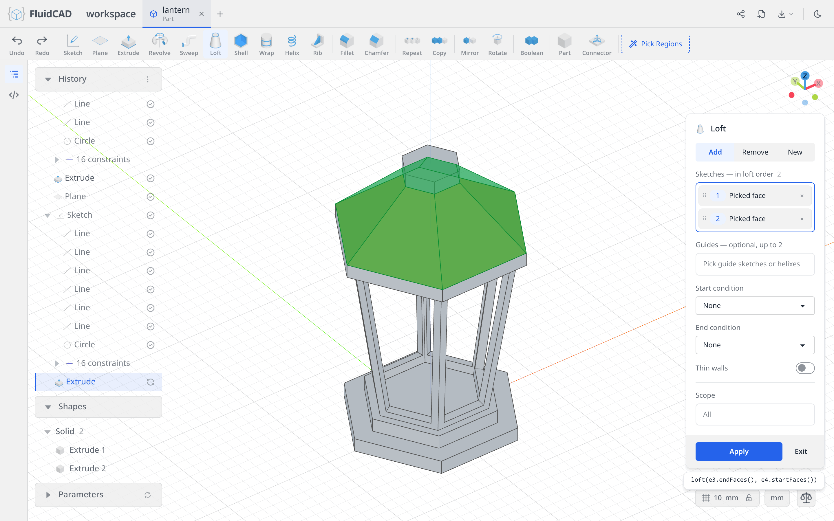
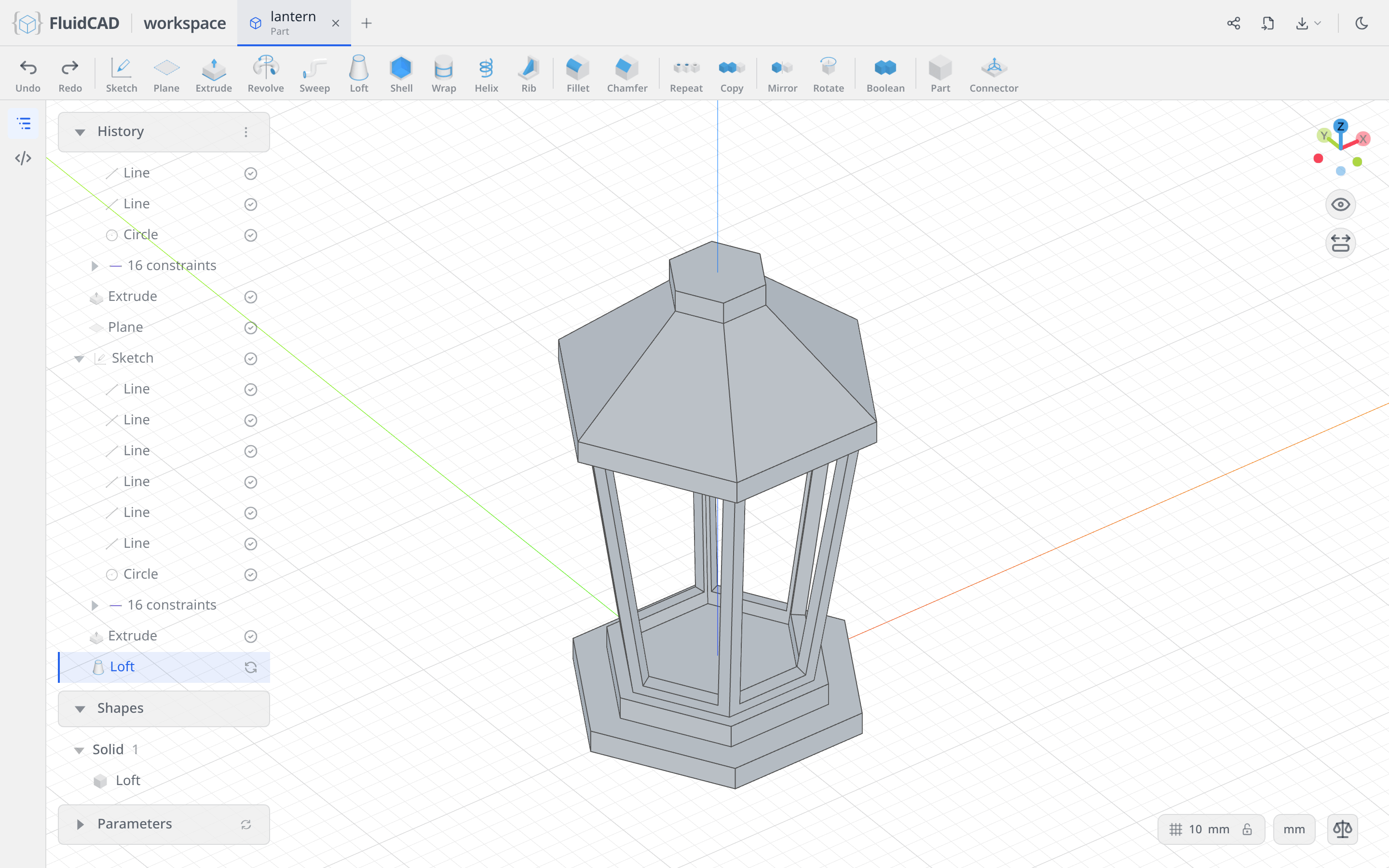
Click Apply. Nothing about the roof was dimensioned — its slope falls out of where the two faces are.
Step 5: The finial and the ring (code only)
The last two features have no tool in the workspace yet: there is no primitive tool for a sphere, no move tool for translate(), and no way to create an offset axis() for a revolve to turn around. So this step is typed, not clicked.
Open the code editor with the </> button on the left rail and add these lines at the end of the file:
let s = sphere(25 / 2)
translate([0, 0, 257], s)

const ringAxis = axis('y', { offsetZ: 290 })

sketch('yz', () => {
    circle([0, 290 + (65 / 2) - (7 / 2)], 7)
})

revolve(ringAxis).new()
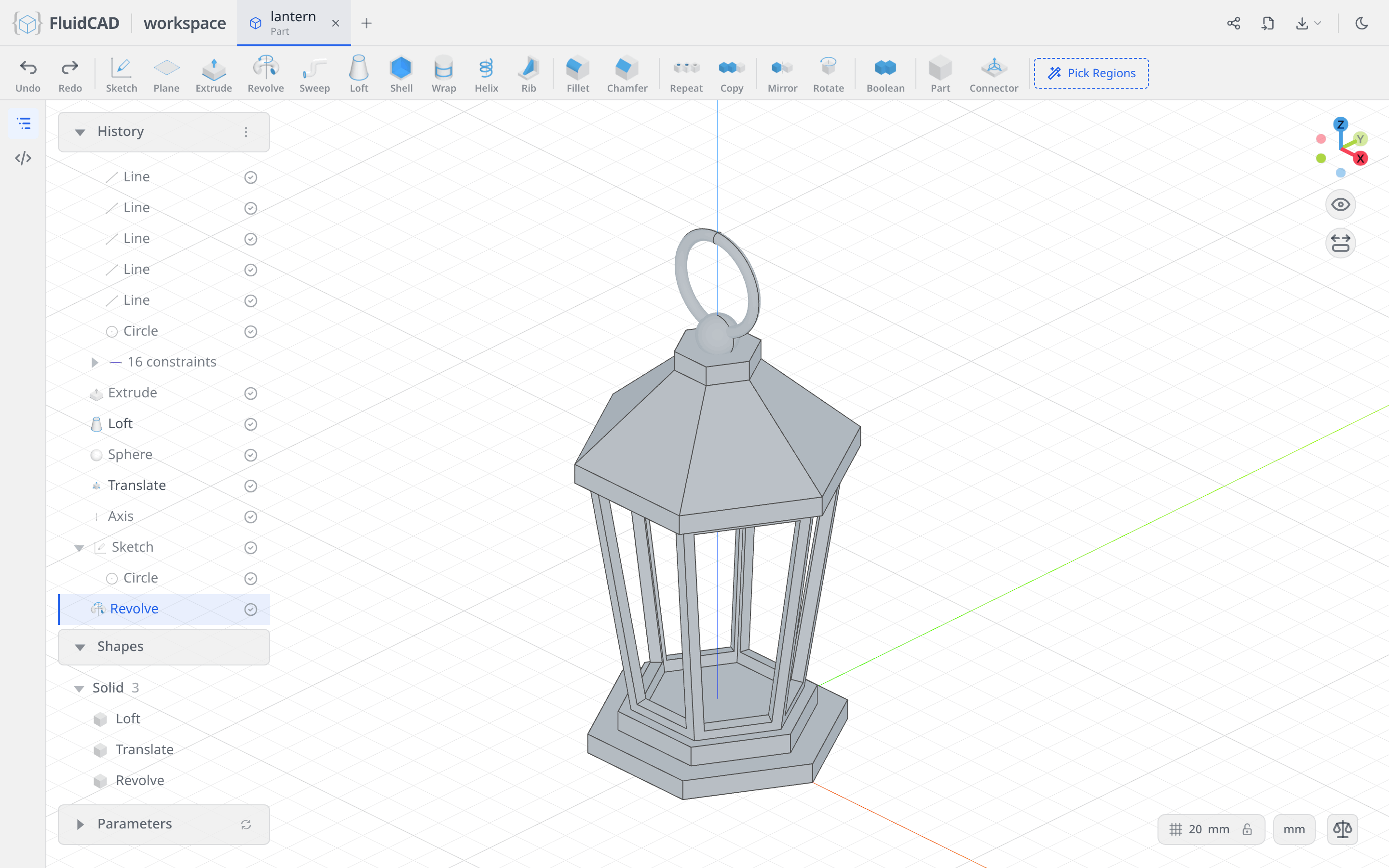
sphere(25 / 2)makes the finial andtranslate()lifts it to z = 257, just above the tip.axis('y', { offsetZ: 290 })is a Y axis raised to z = 290 — the centre line of the ring, well above any geometry.- The ⌀7 circle on the YZ plane is the ring's cross-section, placed 29 mm out from that axis.
revolve(ringAxis)sweeps the circle a full turn around the raised axis, which produces the torus..new()keeps it as its own solid, so it hangs from the finial rather than fusing into it.
Full code
Everything up to the roof was written into lantern.fluid.js by the dialogs — the five polygons, their constraints, the planes, the extrusions, the shell, the projection, the offset, the cut, the repeat and the loft. Open the code editor with the </> button on the left rail or Ctrl+B to read it alongside the model.

The listing below is that file, plus the four hand-typed statements from Step 5. The coordinates you clicked will differ from these, but the constraints make the geometry identical.
Show the full code
import {
    axis, circle, cut, extrude, line, loft, offset, origin,
    plane, project, repeat, revolve, shell, sketch, sphere, translate
} from 'fluidcad/core';
import { coincident, diameter, equal, horizontal } from 'fluidcad/constraints';

// Middle body
const p = plane('xy', 24);
sketch(p, () => {
  const l1 = line([50, 0], [25, 43.3]);
  const l2 = line([25, 43.3], [-25, 43.3]);
  const l3 = line([-25, 43.3], [-50, 0]);
  const l4 = line([-50, 0], [-25, -43.3]);
  const l5 = line([-25, -43.3], [25, -43.3]);
  const l6 = line([25, -43.3], [50, 0]);
  const c1 = circle([0, 0], 100).guide();
  coincident(l1.end(), l2.start());
  coincident(l2.end(), l3.start());
  coincident(l3.end(), l4.start());
  coincident(l4.end(), l5.start());
  coincident(l5.end(), l6.start());
  coincident(l6.end(), l1.start());
  equal(l1, l2, l3, l4, l5, l6);
  coincident(l1.start(), c1);
  coincident(l2.start(), c1);
  coincident(l3.start(), c1);
  coincident(l4.start(), c1);
  coincident(l5.start(), c1);
  coincident(l6.start(), c1);
  diameter(c1, 100);
  coincident(c1.center(), origin());
  horizontal(l2);
});
const e = extrude(150).draft(8).new();
shell(-7, e.endFaces(), e.startFaces());

// Cut windows
sketch(e.sideFaces(1), () => {
  const pj = project(e.sideFaces(1)).guide();
  offset(-6, pj);
});
const f = cut(7);
repeat('circular', 'z', { count: 6, angle: 360 }, f);

// Base
sketch('xy', () => {
  const l7 = line([75, 0], [37.5, 64.95]);
  const l8 = line([37.5, 64.95], [-37.5, 64.95]);
  const l9 = line([-37.5, 64.95], [-75, 0]);
  const l10 = line([-75, 0], [-37.5, -64.95]);
  const l11 = line([-37.5, -64.95], [37.5, -64.95]);
  const l12 = line([37.5, -64.95], [75, 0]);
  const c2 = circle([0, 0], 150).guide();
  coincident(l7.end(), l8.start());
  coincident(l8.end(), l9.start());
  coincident(l9.end(), l10.start());
  coincident(l10.end(), l11.start());
  coincident(l11.end(), l12.start());
  coincident(l12.end(), l7.start());
  equal(l7, l8, l9, l10, l11, l12);
  coincident(l7.start(), c2);
  coincident(l8.start(), c2);
  coincident(l9.start(), c2);
  coincident(l10.start(), c2);
  coincident(l11.start(), c2);
  coincident(l12.start(), c2);
  diameter(c2, 150);
  coincident(c2.center(), origin());
  horizontal(l8);
});
const e2 = extrude(12);
sketch(e2.endFaces(), () => {
  const l13 = line([57.5, 0], [28.75, 49.8]);
  const l14 = line([28.75, 49.8], [-28.75, 49.8]);
  const l15 = line([-28.75, 49.8], [-57.5, 0]);
  const l16 = line([-57.5, 0], [-28.75, -49.8]);
  const l17 = line([-28.75, -49.8], [28.75, -49.8]);
  const l18 = line([28.75, -49.8], [57.5, 0]);
  const c3 = circle([0, 0], 115).guide();
  coincident(l13.end(), l14.start());
  coincident(l14.end(), l15.start());
  coincident(l15.end(), l16.start());
  coincident(l16.end(), l17.start());
  coincident(l17.end(), l18.start());
  coincident(l18.end(), l13.start());
  equal(l13, l14, l15, l16, l17, l18);
  coincident(l13.start(), c3);
  coincident(l14.start(), c3);
  coincident(l15.start(), c3);
  coincident(l16.start(), c3);
  coincident(l17.start(), c3);
  coincident(l18.start(), c3);
  diameter(c3, 115);
  coincident(c3.center(), origin());
  horizontal(l14);
});
extrude(12);

// Top
const p2 = plane('xy', 174);
sketch(p2, () => {
  const l19 = line([82.5, 0], [41.25, 71.45]);
  const l20 = line([41.25, 71.45], [-41.25, 71.45]);
  const l21 = line([-41.25, 71.45], [-82.5, 0]);
  const l22 = line([-82.5, 0], [-41.25, -71.45]);
  const l23 = line([-41.25, -71.45], [41.25, -71.45]);
  const l24 = line([41.25, -71.45], [82.5, 0]);
  const c4 = circle([0, 0], 165).guide();
  coincident(l19.end(), l20.start());
  coincident(l20.end(), l21.start());
  coincident(l21.end(), l22.start());
  coincident(l22.end(), l23.start());
  coincident(l23.end(), l24.start());
  coincident(l24.end(), l19.start());
  equal(l19, l20, l21, l22, l23, l24);
  coincident(l19.start(), c4);
  coincident(l20.start(), c4);
  coincident(l21.start(), c4);
  coincident(l22.start(), c4);
  coincident(l23.start(), c4);
  coincident(l24.start(), c4);
  diameter(c4, 165);
  coincident(c4.center(), origin());
  horizontal(l20);
});
const e3 = extrude(12);
const p3 = plane('xy', 238);
sketch(p3, () => {
  const l25 = line([25, 0], [12.5, 21.65]);
  const l26 = line([12.5, 21.65], [-12.5, 21.65]);
  const l27 = line([-12.5, 21.65], [-25, 0]);
  const l28 = line([-25, 0], [-12.5, -21.65]);
  const l29 = line([-12.5, -21.65], [12.5, -21.65]);
  const l30 = line([12.5, -21.65], [25, 0]);
  const c5 = circle([0, 0], 50).guide();
  coincident(l25.end(), l26.start());
  coincident(l26.end(), l27.start());
  coincident(l27.end(), l28.start());
  coincident(l28.end(), l29.start());
  coincident(l29.end(), l30.start());
  coincident(l30.end(), l25.start());
  equal(l25, l26, l27, l28, l29, l30);
  coincident(l25.start(), c5);
  coincident(l26.start(), c5);
  coincident(l27.start(), c5);
  coincident(l28.start(), c5);
  coincident(l29.start(), c5);
  coincident(l30.start(), c5);
  diameter(c5, 50);
  coincident(c5.center(), origin());
  horizontal(l26);
});
const e4 = extrude(12);
loft(e3.endFaces(), e4.startFaces());

// Finial and ring — typed by hand: spheres, translate and axes have no tool yet
let s = sphere(25 / 2);
translate([0, 0, 257], s);

const ringAxis = axis('y', { offsetZ: 290 });

sketch('yz', () => {
  circle([0, 290 + (65 / 2) - (7 / 2)], 7);
});

revolve(ringAxis).new();
What you practiced
-
The Polygon tool with a typed diameter and side count, and its Inscribed option, which decides whether the diameter is measured across the corners or across the flats
-
Plane at an offset, three times, as scaffolding for geometry that does not sit on an origin plane — and the rule that a plane leaves the viewport once a sketch uses it, while its timeline row keeps it pickable
-
Draft on an extrusion, and the New tab, which keeps a solid separate so its faces stay easy to reference
-
Shell by picking the faces to remove, with a negative thickness that grows the wall inward
-
Project to bring a model face into a sketch as fixed reference geometry, and Guide to keep it out of the profile
-
The 2D Offset tool with a negative distance, deriving a window from the face it sits on instead of dimensioning it
-
Repeat → Circular, which re-applies a whole cut around an axis rather than copying the solid
-
Sketching on a face the model already has, and reading the Face — Extrude chip that keeps the reference alive through edits
-
Loft between two picked faces, where the shape of the roof is decided entirely by where its two ends are