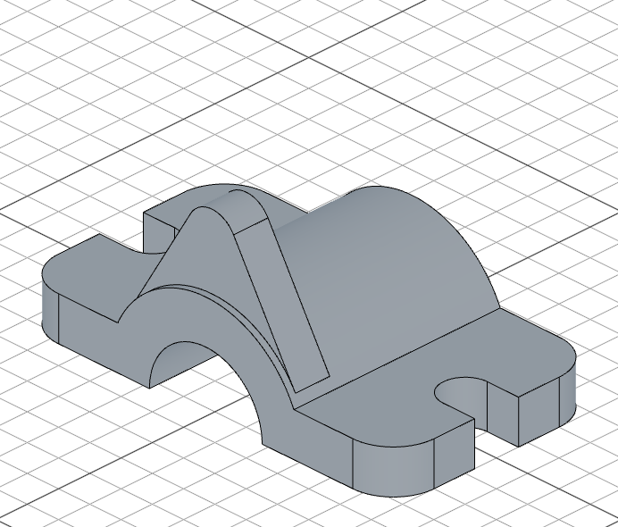
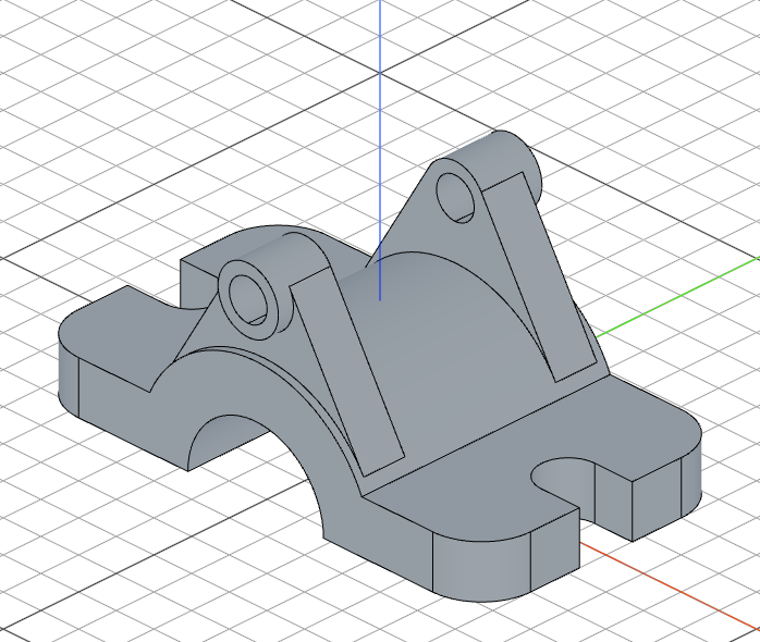
Building an Upper Alignment Clamp

In this tutorial, you'll build an upper alignment clamp from scratch, based on the original design by TooTallToby. It covers tangent lines and arcs, geometric constraints, projecting and guiding geometry, symmetric extrusions, drilling, and mirror repeats.
Create a new file called upper-alignment-clamp.fluid.js in your project.
Setup
Start with imports. This model uses three import sources — core operations, geometric constraints, and selection filters.
import { aLine, arc, circle, color, connect, copy, cut, extrude,
    fillet, fuse, hLine, hMove, mirror, move, plane, project, rect,
    remove, repeat, rotate, select, shell, sketch, slot, tArc, tLine,
    vMove } from "fluidcad/core";
import { enclosed, enclosing, outside } from "fluidcad/constraints";
import { edge, face } from "fluidcad/filters";
fluidcad/core— all the modeling operations (sketch, extrude, cut, etc.)fluidcad/constraints— geometric constraints for tangent lines (outside,enclosing)fluidcad/filters— selection filters for edges and faces
Step 1: The base body
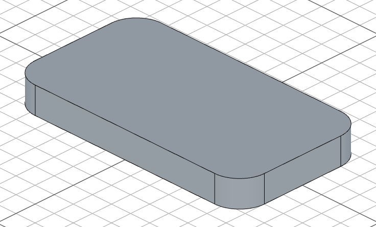
The clamp starts as a rounded rectangular block.
rect("top", 120, 66).centered().radius(13)
let e = extrude(13)
rect("top", 120, 66) draws a 120 x 66 rectangle on the top plane. .centered() centers it on the origin. .radius(13) rounds all four corners with a 13-unit fillet. extrude(13) pushes it up 13 units. We store the result in e to reference its faces later.
Step 2: Cut the side notches
Each side of the clamp has a notch cut into it. We'll create one notch and mirror it.
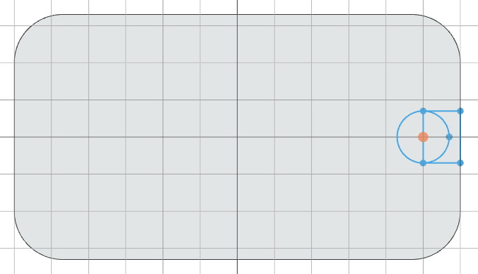
Sketch the notch profile
sketch(e.endFaces(), () => {
    hMove(120 / 2 - 10)
    rect(10, 14).centered('vertical')
    circle(14)
});
e.endFaces() gives us the top face of the base. hMove(120 / 2 - 10) moves the cursor to 10 units from the right edge. rect(10, 14).centered('vertical') draws a 10 x 14 rectangle centered vertically. circle(14) adds a semicircular end to the notch.
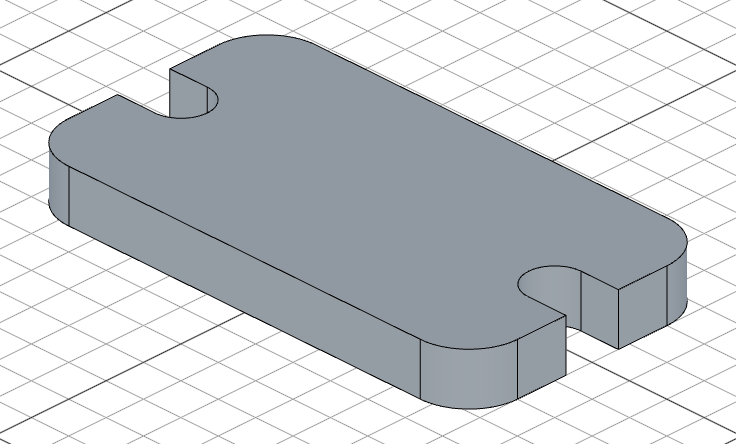
Cut and mirror
const notch = cut()

repeat("mirror", "yz", notch);
cut() removes the sketched material all the way through. repeat("mirror", "yz", notch) mirrors the notch across the YZ plane, creating a matching notch on the opposite side.
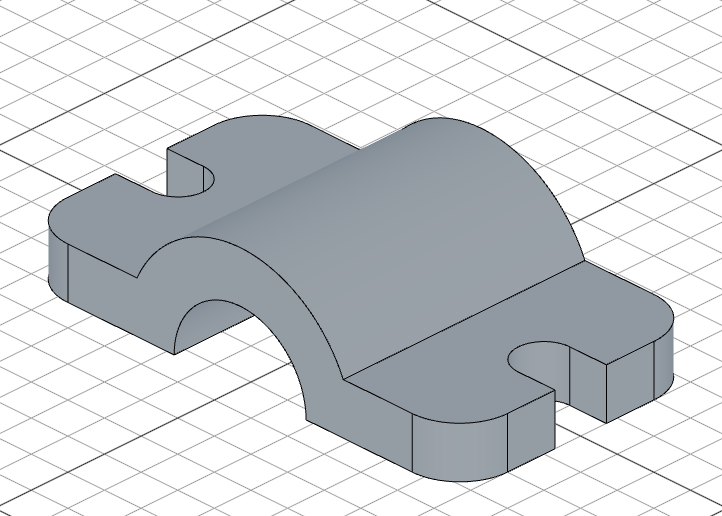
Step 3: The cylindrical bore
A large cylindrical bore runs through the center of the clamp body.
Sketch the semicircle
sketch("front", () => {
    arc(31)
    connect()
    move([0, 0])
});
arc(31) draws a semicircular arc with radius 31 on the front plane. connect() closes the profile by drawing a straight line between the arc endpoints. move([0, 0]) positions the sketch at the origin.

Extrude and bore
const circleExtrude = extrude(66).symmetric();
cut(66, circle("front", 36)).symmetric();
extrude(66).symmetric() extrudes the semicircle 33 units in both directions (66 total, centered). We store it as circleExtrude because we'll reference its edges later. cut(66, circle("front", 36)).symmetric() then bores a 36-diameter hole through the center, also symmetric. This creates the clamp's main bore.
Step 4: The pipe mount
The pipe mount is the most complex step — it uses projected geometry, tangent lines with constraints, and tangent arcs to create a smooth profile connecting the bore to a pipe.
Create the sketch plane
const p = plane("front", { offset: 20 })
plane("front", { offset: 20 }) creates a plane 20 units in front of the front plane.
Build the profile with tangent geometry
sketch(p, () => {
    const arc = project(circleExtrude.endEdges(edge().arc())).guide()
    vMove(45)
    const c = circle(16).guide()
    const l1 = tLine(outside(arc), outside(c))
    const l2 = tLine(enclosing(arc), enclosing(c))
    tArc(l1.end())
    tArc(l1.start(), l2.start(), l1.tangent())
});
This sketch builds the pipe mount profile in several steps:
project(circleExtrude.endEdges(edge().arc())).guide()projects the bore's end edge onto the sketch plane as a construction (guide) arc — it's visible for reference but won't become part of the solidvMove(45)moves the cursor up 45 units, thencircle(16).guide()places a guide circle there — this defines the pipe positiontLine(outside(arc), outside(c))draws a tangent line on the outer sides of both circles using theoutsideconstrainttLine(enclosing(arc), enclosing(c))draws a tangent line on the inner (enclosing) sides using theenclosingconstrainttArc(l1.end())closes the top with a tangent arctArc(l1.start(), l2.start(), l1.tangent())connects the two tangent lines at the bottom with a smooth arc, using the tangent direction froml1to ensure continuity

Extrude the mount
extrude(11)
This pushes the profile 11 units to create the solid pipe mount.
Step 5: The pipe through-hole and mirror
Now we add the pipe itself with a through-hole, then mirror the entire mount to the other side.
Sketch the pipe profile
sketch(plane("front", { offset: 35 }), () => {
    move([0, 45])
    circle(16)
    circle(10);
});
On a plane 35 units from the front, two concentric circles are drawn at the pipe center (0, 45): an outer circle of radius 16 and an inner circle of radius 10.

Extrude and drill
const pipeLength = -35 + 20;
const e2 = extrude(pipeLength).drill(false);

cut(-pipeLength, circle(e2.startFaces(), 10));
extrude(pipeLength) extends the pipe backward (negative direction). .drill(false) creates a hollow extrusion — the inner circle becomes a hole, but false means it doesn't drill into existing geometry below. Then cut(-pipeLength, circle(e2.startFaces(), 10)) bores the inner hole through, using a circle sketched on the start face.
Mirror everything
mirror("front")
mirror("front") mirrors the pipe mount and through-hole across the front plane, creating a symmetric clamp with pipe mounts on both sides.
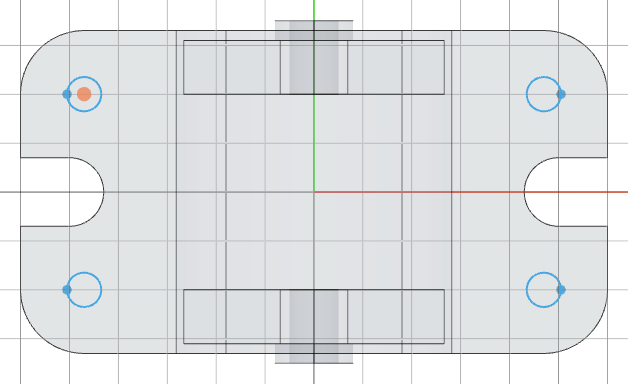
Step 6: Mounting holes and counterbores
The final step adds four mounting holes with counterbores in the corners of the base.
Through-holes
sketch(e.endFaces(), () => {
    const center = [120 / 2 - 13, -66 / 2 + 13];
    move(center)
    circle(7);
    mirror("x")
    mirror("y")
}).name('Hole Sketch');

cut().name('Hole')
A circle of radius 7 is placed 13 units inset from one corner of the base. mirror("x") mirrors it horizontally, then mirror("y") mirrors both vertically — creating four holes from one. cut() removes material all the way through. .name() labels the operations in the model tree.
Counterbores
sketch(e.endFaces(), () => {
    move([120/2-13, -66/2+13])
    circle(15)
    mirror("x")
    mirror("y")
}).name('Counterbore Sketch');

cut(4).name('Counterbore')
Larger circles (radius 15) at the same positions create the counterbore — a wider, shallow recess for bolt heads. cut(4) removes only 4 units of depth.
Full code
import { aLine, arc, circle, color, connect, copy, cut, extrude, fillet, fuse, hLine, hMove, mirror, move, plane, project, rect, remove, repeat, rotate, select, shell, sketch, slot, tArc, tLine, vMove } from "fluidcad/core";
import { enclosed, enclosing, outside } from "fluidcad/constraints";
import { edge, face } from "fluidcad/filters";

rect("top", 120, 66).centered().radius(13)
let e = extrude(13)

sketch(e.endFaces(), () => {
    hMove(120 / 2 - 10)
    rect(10, 14).centered('vertical')
    circle(14)
});

const notch = cut()

repeat("mirror", "yz", notch);

sketch("front", () => {
    arc(31)
    connect()
    move([0, 0])
});

const circleExtrude = extrude(66).symmetric();
cut(66, circle("front", 36)).symmetric();

const p = plane("front", { offset: 20 })

sketch(p, () => {
    const arc = project(circleExtrude.endEdges(edge().arc())).guide()
    vMove(45)
    const c = circle(16).guide()
    const l1 = tLine(outside(arc), outside(c))
    const l2 = tLine(enclosing(arc), enclosing(c))
    tArc(l1.end())
    tArc(l1.start(), l2.start(), l1.tangent())
});

extrude(11)

sketch(plane("front", { offset: 35 }), () => {
    move([0, 45])
    circle(16)
    circle(10);
});

const pipeLength = -35 + 20;
const e2 = extrude(pipeLength).drill(false);

cut(-pipeLength, circle(e2.startFaces(), 10));

mirror("front")

sketch(e.endFaces(), () => {
    const center = [120 / 2 - 13, -66 / 2 + 13];
    move(center)
    circle(7);
    mirror("x")
    mirror("y")
}).name('Hole Sketch');

cut().name('Hole')

sketch(e.endFaces(), () => {
    move([120/2-13, -66/2+13])
    circle(15)
    mirror("x")
    mirror("y")
}).name('Counterbore Sketch');

cut(4).name('Counterbore')
What you practiced
rect().centered().radius()— creating a centered rectangle with rounded corners.endFaces()— referencing the top face of an extrusion for follow-up sketchescut()+repeat("mirror")— cutting and mirroring geometry across a planearc()+connect()— drawing a semicircular profile and closing it.symmetric()— extruding or cutting in both directions from the sketch planeproject().guide()— projecting existing edges as construction geometrytLine()withoutside/enclosing— drawing tangent lines with geometric constraintstArc()— connecting tangent lines with smooth arcsextrude().drill()— creating hollow extrusionsmirror()— mirroring geometry across a standard planemirror("x")/mirror("y")in sketches — mirroring sketch geometry to create symmetric patterns.name()— labeling operations in the model tree