User Interface
The workspace is one browser tab: a top bar with the open files, a toolbar, a panel column on the left, and the viewport. The same layout serves parts and assemblies; the toolbar and the panels change with the kind of file that is open.
The part workspace
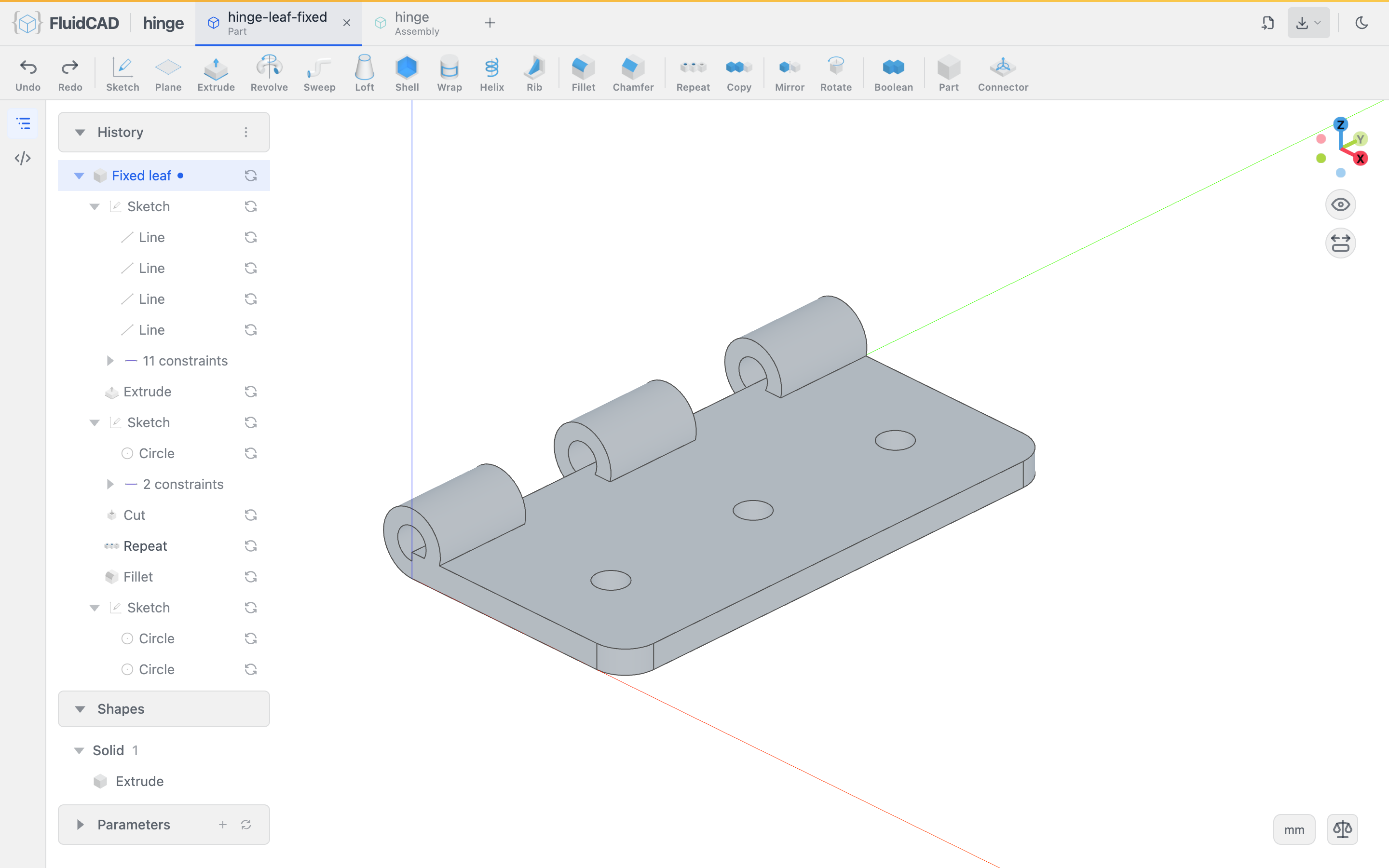
- 1File tabsEvery open file is a tab. The current model tab owns the viewport; drag to reorder, right-click to rename.
- 2+ (Open a file)Opens a box listing every file in the workspace. Pick one to open it as a tab, or type a name that does not exist to create it.
- 3ImportImports a STEP file into imports/ and appends a load() statement.
- 4ExportLists the scene’s solids; pick one for the STEP / STL / PNG dialog. In an assembly the list leads with Whole assembly.
- 5ToolbarSketch, the create features (Extrude … Rib), the pick tools (Fillet, Chamfer, Shell, Offset), datums and transforms, Boolean, and the structure tools Part and Connector. Undo / Redo sit at the left end.
- 6Feature treeShows or hides the panel column.
- 7Code editorDocks the source editor on the left (Ctrl+B). The editor takes width from the viewport rather than covering it.
- 8HistoryOne row per feature, in file order. See below for what clicks do.
- 9History menuRecompute scene (clears the cache and rebuilds everything) and Show execution time.
- 10ShapesOne row per solid. Click to select it; the row menu hides it, sets transparency, or exports it.
- 11ParametersOne control per param(). + adds a parameter, the arrow resets all to their defaults.
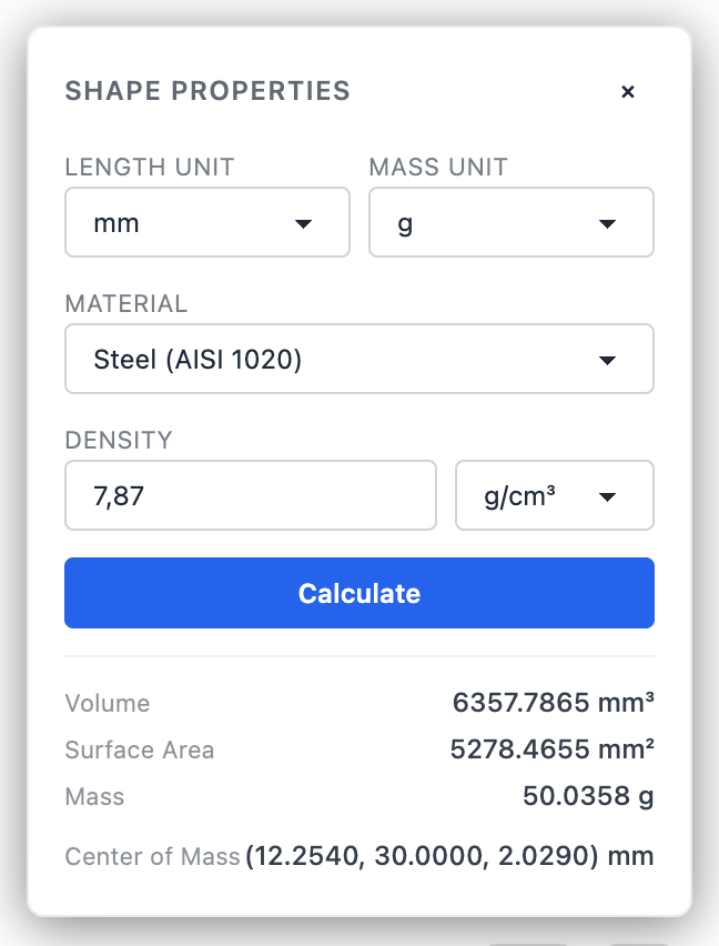
- 12Shape propertiesVolume and mass of the selected solid, for a chosen material.
- 13UnitThe document unit. Readouts and dialogs use it; the menu switches the display to mm / in / same as project.
- 14View cubeClick a face or an axis dot for that view. Below it: fit to view, and the grid / projection toggles.
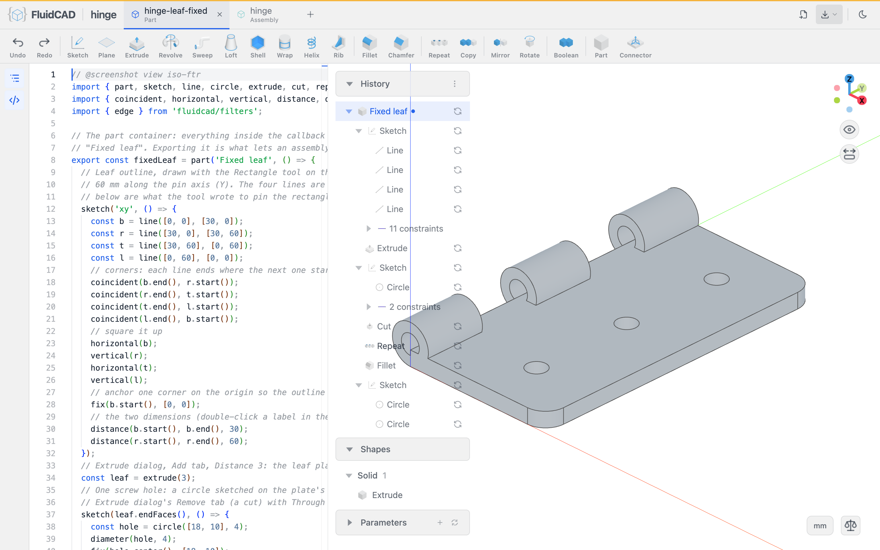
With the code editor open, the file sits between the rail and the panels. Edits in the editor re-render on save, and features applied from the dialogs appear in the editor as they are written:
Settings
The gear in the top bar, just before the light/dark switch, opens the global settings. They are yours rather than the project's, and they apply everywhere FluidCAD runs for you: the browser, the VS Code extension and the desktop app. Edits wait for Save; a tab with an unsaved edit shows a dot, and Cancel drops the edits.
| Tab | What it holds |
|---|---|
| Appearance | Dark or light theme. The sun and moon button in the top bar switches it too. |
| Editor | The code editor's font, picked from the monospace fonts installed on the computer, its size, word wrap, and whether the editor pane opens when FluidCAD starts (off by default). |
| Sketch | The snap radius and the pick radius, in screen pixels: how close the cursor has to be for the sketcher to snap to a vertex, axis or grid line, and for a line, arc or vertex to highlight under it. |
| Timeline | Which rows the History panel lists under a sketch: all of its children or only the editable features (the ones with an edit dialog, such as offset, projection and intersect), whether its N constraints group shows (on by default), and whether its N regions group shows (off by default). |
| Units | The unit new projects are created in. Existing projects keep theirs; change those from the unit chip at the bottom of the viewport. |
| Advanced | Reset every setting to its default, after a confirmation. This one acts at once rather than on Save. |
Project settings, such as the engine pin and the project unit in fluidcad.json, are not here; see Project configuration.
The History panel
The History panel is the feature timeline. Every statement in the file is a row: sketches fold their geometry, an N constraints group and an N regions group (the region declarations for extrude-family picks; the group is off by default), parts fold their features plus N connectors and N exposed groups. The Timeline tab of the settings picks which of a sketch's rows are listed. The glyph on the right of a row says whether the feature was served from cache (check) or rebuilt (refresh arrows). A sketch, plane or axis a feature has used is dimmed — the feature took it off the screen — and carries an eye on hover: click it to draw the object again, and again to hide it. The eye is view state only; nothing in the file changes.
-
Single click a row to roll the model back to that feature. The viewport shows the model as it was right after that row, and the toolbar shrinks to what makes sense there. Click the last row, or edit the file, to come back.
-
Double-click a row to edit the feature: a breakpoint is placed after it, so the model rolls back to that point, and the feature's dialog opens with its current values. Apply writes the change into the existing statement.
-
Right-click a row for its menu:
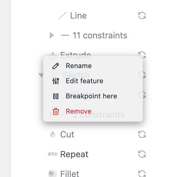
Rename edits the feature's
.name('…')in place. Edit feature is the double-click action; on a sketch row it reads Edit sketch, takes a.close()chain off the statement and reopens the sketch at a breakpoint. Breakpoint here puts abreakpoint()after the row without opening a dialog, so features you add next land after that row instead of at the end of the file. Remove deletes the statement; if later features depend on it, a dialog lists them and deletes the closure on confirm. -
The ⋮ menu on the panel header:
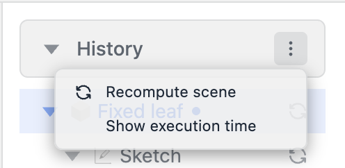
Recompute scene clears the geometry cache and rebuilds every feature from scratch. Use it when a cached result looks stale. Show execution time annotates each row with its build time, and marks whether it was rebuilt or came from the cache.
Breakpoints
A breakpoint() statement stops evaluation at that line. The viewport shows the model up to that point, and anything the toolbar writes is inserted before the breakpoint rather than at the end of the file. Remove the statement to resume the full model. Besides the History menu, VS Code inserts one from the gutter and Neovim with :FluidCadToggleBreakpoint.
Shapes and shape properties
The Shapes panel lists the solids the model produced, grouped by type. Clicking a row selects the solid in the viewport; the row menu toggles visibility, sets transparency, and opens the export dialog for that solid.
The scale icon at the bottom right opens Shape properties. Select a solid, pick a material (or type a density), and Calculate reports its volume and mass in the chosen units.
Parameters
The Parameters panel shows one control per param() in the file: a number field, slider, text box, dropdown, checkbox or color swatch, according to the declared type. Changing a control writes the new value into the source and re-renders. + declares a new parameter through a dialog, and the arrow resets every value to its default. See Param.
Edges in the viewport
The viewport draws the edges of the model as lines. Two kinds of B-rep edge are not model edges and are treated accordingly:
- Seams — the line where a cylinder, cone or sphere's surface closes on itself — are never drawn. They are not selectable either:
select(edge()), the feature accessors such assideEdges(), andedgeCount()never return or count one, so a boss looks and behaves the same whichever way its sketch plane happened to orient the seam. - Tangent edges — where two faces meet smoothly, as at a fillet's boundary or where a flat flank runs into a cylinder — are drawn like every other edge and remain selectable. Setting
dimTangentEdgestotruein the preferences file draws them dimmed, pulled toward the face colour, so only real creases read as lines.
Measuring
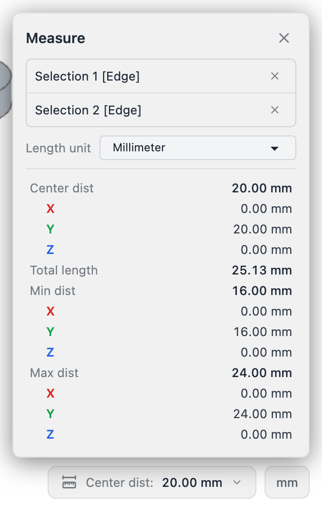
There is no measure tool to arm. Click a face, edge or vertex in the viewport and a status bar appears with its type and its measurement (area for a face, length for an edge). Ctrl+click or Shift+click adds entities: two faces give the minimum and maximum distance between them, two parallel faces the parallel distance, two cylinders the axis distance, two edges an angle.
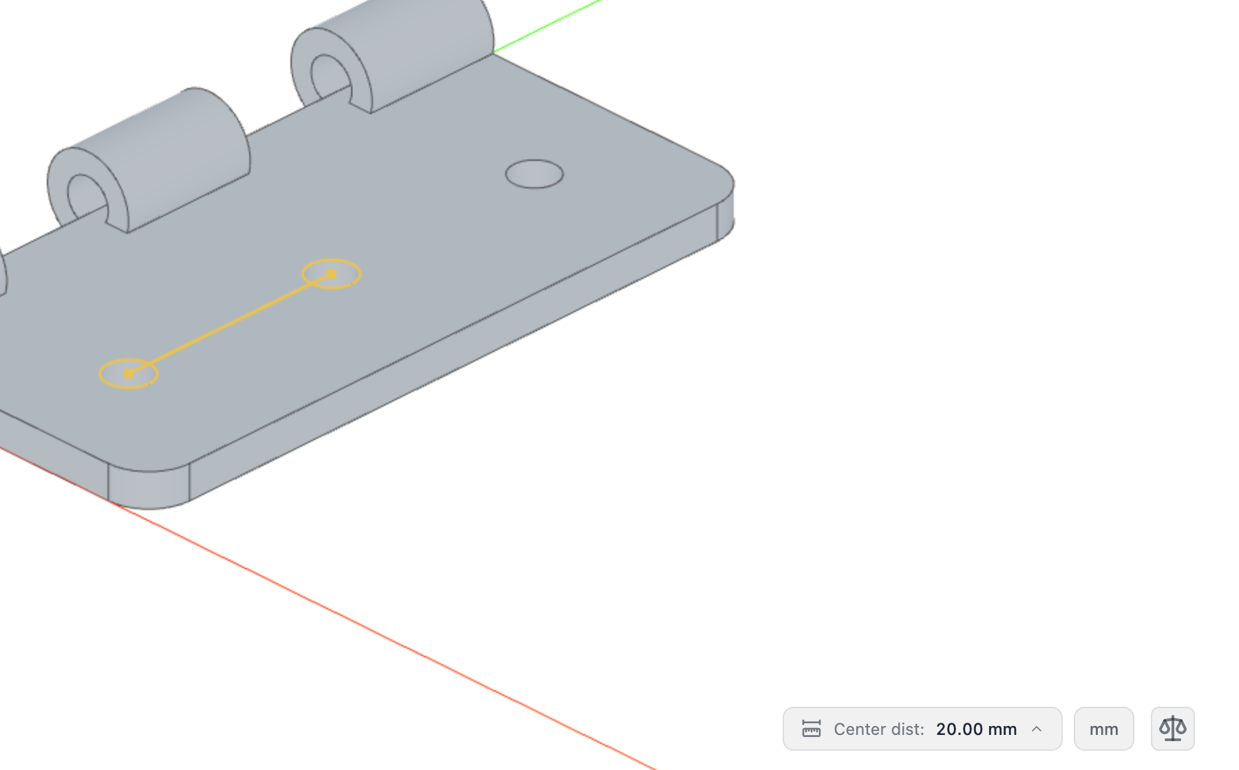
Click Show all measurements on the status bar for the full panel, with one card per selected entity and the pairwise results.
Measuring works the same in an assembly: click any part's face or edge, and the live pose of the instance is taken into account.
The assembly workspace
Opening a .assembly.js file swaps the toolbar for the assembly tools and the panels for the assembly rail.
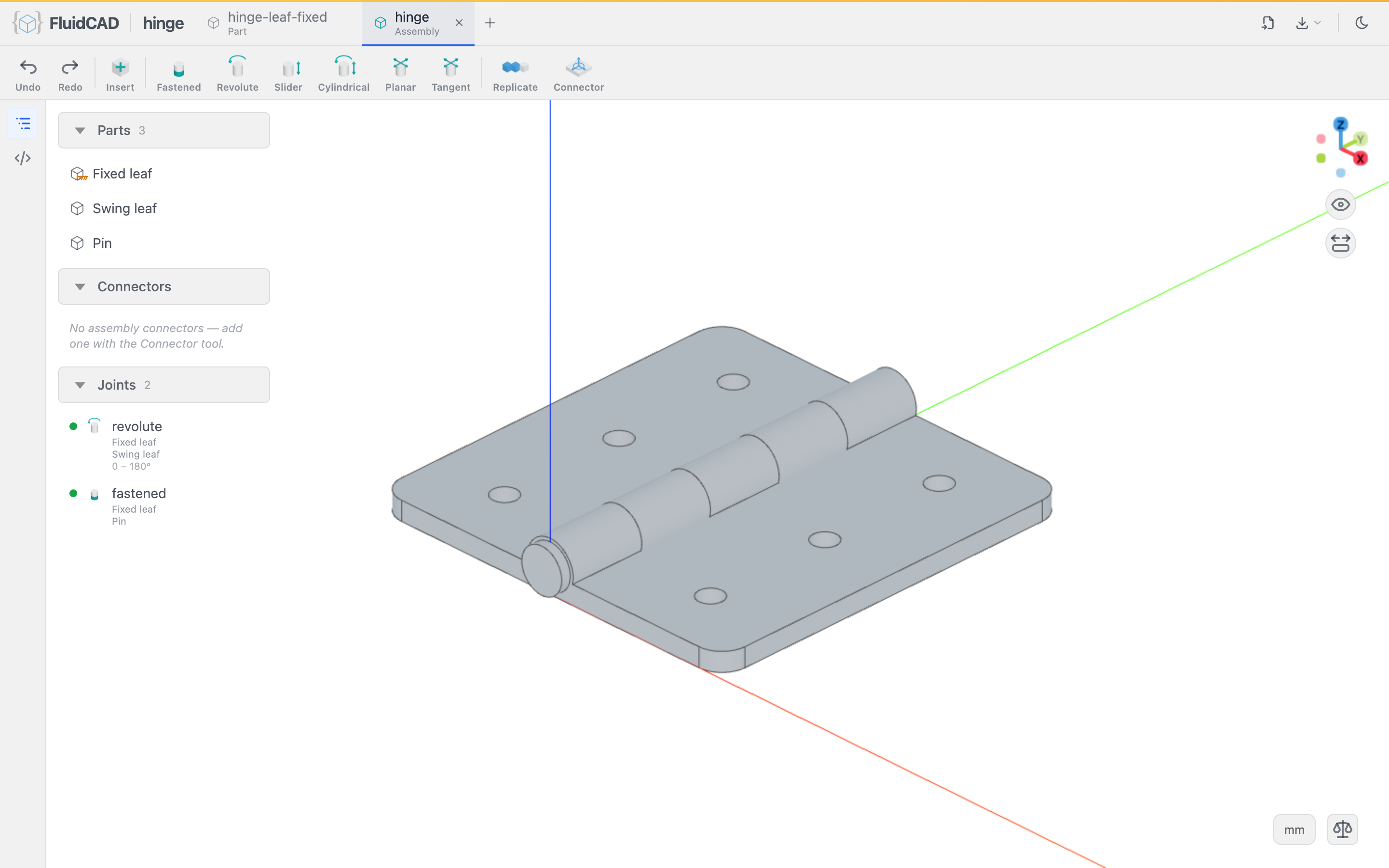
- Toolbar: Insert (a dialog listing every part and sub-assembly in the workspace), the joints Fastened, Revolute, Slider, Cylindrical, Planar, Tangent, then Replicate and Connector (a free frame in assembly space).
- Parts: one row per inserted instance; the eye hides it, the menu offers Show in source, Toggle grounded, Rename and Delete. Sub-assemblies group their members under a header.
- Connectors: the assembly-level connectors declared in this file.
- Joints: one row per
mate(), with the two parts and the limits. Click a row to highlight both connectors; the menu offers Animate… (revolute and slider), Edit mate…, Suppress, Delete and Show in source. - Instances are moved by dragging them, or with the gizmo's arrows and rings; the new pose is written back to the
insert()statement. Dragging a jointed part moves it within the joint's freedom.
See Assembly for the joints and the Getting started chain for the full flow.
Undo and redo
Every toolbar operation is one edit to the source file, so Undo and Redo step the editor's own history: the first two buttons on the toolbar, Ctrl+Z and Ctrl+Shift+Z (Ctrl+Y also redoes; on macOS use ⌘). The keys work in both workbenches with the viewport focused; inside the code editor or a text field they keep their native meaning. The group appears once an editor is attached — the in-page editor, or the VS Code / Neovim extension.
Editors
The in-page editor is enough for most work: it completes against the engine's own type declarations and shows diagnostics inline. The VS Code and Neovim extensions drive the same server from your editor; see Editor setup.